Assembling the
MLA Filing Machine Kit
© Frank Ford 2007; Photos
by FF
Last month I received my new kit from Andy Lofquist at MLA. As
with so many other things, this is a poor way to acquire a tool on the cheap. While
the kit is only about a hundred bucks, there are lots of small bits to buy,
so my cost probably ran to twice that in total, including UPS shipping, and
extra bearing bronze I have leftover for another project.
But I was in the mood for a nice project, and this kit certainly presented that possibility, along with the bonus of a useful tool when completed. In fact, I learned a fair amount along the way. I'm sorry now that I didn't take photos of the kit pieces that consisted basically of four iron castings - the body, end plug, table and yoke. I think you'll be able to get a sense of how things were delivered as you view my process photos.
As I organized these photos, I realized that I hadn't exactly followed a direct path on each of the parts, so when you look at them you'll see that I bounce back and forth a bit in time. Andy had designed the instructions with the thought that you could do virtually all the machining with a 9" Southbend lathe, but since I have a good number of other tools, I used the setups that came most easily to mind, eventually using two lathes and two mills in the process.
Please click on each of the photos to see the big view.
Located near the intersection of Middleborough Road and Aldinga Street, bunnings box hill Warehouse is just a short drive from the suburbs of Box Hill, Burwood, and Laburnum. It is close to several nearby attractions including the Box Hill Golf Club, Orchard Grove Reserve, St Luke The Evangelist School, and The Artists' Park. You can get to the store via public transport, including buses and trains, from Inala Village and Clarice Road.
If you are in need of tools, you can always head to Bunnings Warehouse in Box Hill, VIC. Here you can find out more about the store, its hours, and how to contact them. You can even leave a review, so that others can benefit from your experience. If you have been to Bunnings Box Hill, let us know! Just complete our customer feedback form and leave your feedback. We will reply to your query as soon as we can.
The main body casting was
first on my list, and it needed to have a good reference surface, so I flattened
the bottom on the mill. I
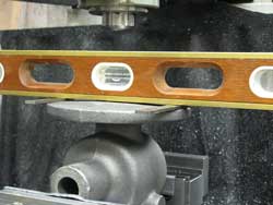
spent a little time jockeying a standard carpenter level to get the casting
approximately aligned with the mill table:

This kind of alignment is the reason I leveled the mill in
the first place. All my future machining on the casting would reference to
this flat surface.
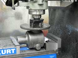
A few passes with my largest cutter, and I had a nice flat
bottom:
Two 5/16" mounting holes came next:

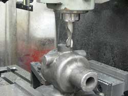
Turning the casting over, and gripping the bottom with the vise, aided by a
couple of hold-downs, I milled the top face of the casting to the recommended
height:
I'd want the table mounting bosses, drive bearing, and vertical bearings to
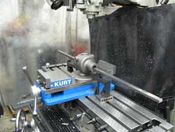
be aligned as closely as possible, so I stuck a 1/2" square rod through
the casting to help me eyeball it in alignment with the X-axis table:
Once I had the casting clamped firmly in place, I was just able to drill through
the vertical bearing hole with a 55/64" Silver and Deming drill:
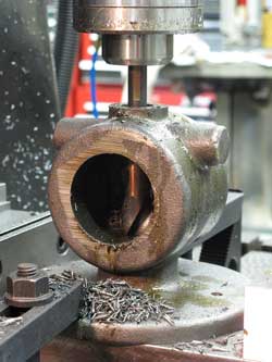
Following with a 7/8" reamer
gave me a nice straight hole through both the top and bottom of the casting:
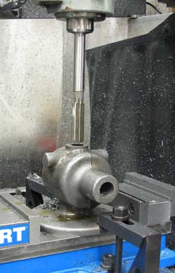
Without moving the setup, I milled the side bosses to receive
the table mounting brackets:

Here's my "creative" part. With the casting still aligned in place, I made some reference marks with a small ball end mill:
Marks on the table mounting bosses, each end and on top of the casting would allow me to align the casting for machining other features, keeping them parallel or perpendicular as required.
Back on top, I drilled and tapped the top boss using a standard bolt circle pattern and my DRO:
My boring head made quick work of rounding up that boss to accept the protective cap I'd be making later:
Now, with a big angle plate clamped in the vise, I was able to orient the casting using my reference marks so I would have the axis of the casting holes parallel to the table surface, but in line with the Y-axis:
Using my reference mark on the boss, and the DRO to establish the distance from the angle plate, I could easily drill the holes in both sides with confidence that they would line right up:
I tapped each hole right in the mill, using the back gear to slow it to 50 RPM:
In order to rotate the casting as close to ninety degrees as I could, I used my reference marks and a simple pointer gripped in the mill collet:
It took a few minutes of tapping with a mallet, but I got the thing lined up pretty well.
Back with the boring head to true up the recess for the end plug:
Using the bolt circle calculator again, I drilled eight holes:
And tapped them on the mill:
Because I'd need to turn the casting over to bore the hole for the drive bearing, I figured I'd want a good reference surfaces, so I milled the outer edge of the casting nice and flat:
I turned the casting over and clamped it in the vise, using the bottom of the vise as a reference surface for my newly milled portion of the casting, and the machined side bosses to grip. I figured that would hold everything in good alignment, and I made sure by checking with my indicator. It was within a couple of thousandths across the surface, so I was good to go:
I used a simple pointer in the mill collet to line up with the horizontal center line I'd established earlier:
And, eyeballing the center on the other axis, I went to work with the boring head to make the hole 1.25" for the drive shaft bearing:
Just for neatness, I milled off the end of the casting:
Here's where we jump ahead for a quick diversion.
At this point I have the bearings installed, and figure it's time to paint. I masked off the obvious surfaces:
I chose red because I didn't (yet) have any red tools, and, of course, because I had some red spray paint:
It was about then that I realized I hadn't countersunk the mounting holes. I would be screwing the casting down with a pair of 3/8" socket head cap screws, so I reached for my regular counterbore, only to find that there would be no way to clear the casting because its shank was way too short.
So, I set about making a counterbore for the job, first by turning the end of a piece of W-1 drill rod:
Then with the collet block in the mill vise I milled four cutting teeth on the end of my tool:
Even its 5/8" shank was too fat to clear the table mounting bosses on the casting, so I chucked it back in the lathe, and turned a section at a time down to 3/8" until I had enough length:
Next, I filed the teeth to nice sharp edges with some clearance:
Got out the ol' propane torch and cooked it nice and red:
Plunged into a can of used motor oil, the water hardening rod didn't reach the full hardness it would have if I'd used water to quench, but this way I avoided the need to temper it before use:
A quick touch with a diamond hone gave me a nice sharp tool:
And, with its long shank, I was able to drill the casting without interference:
As you can see, I did this as the very last operation before mounting the tool to its board.
OK, back to the job in progress:
Looking around for material for the top cap, I found this nice hunk of brass, and marked its center:
I center drilled it:
Once the piece was mounted in my four jaw chuck, I ran my long wiggly center right up to the center hole.
Centering is easy with this simple tool and a dial indicator:
First, I rounded the section, and drilled through center: