Click the pix:
|
|
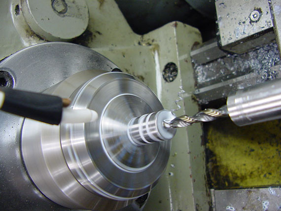
I made up a few blanks, about 1-3/4" long, and drilled out the shaft end to relieve it for the truss rod as it is threaded. This hole is 13/64" |
|
|
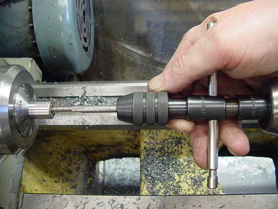
Then, I drilled and tapped the business end to 10-32. Here, I wish I had a tap that was just a teeny bit undersize, I think, so the threaded rod wouldn't come out too fat. Anyhow, I think that will be a smallish problem. |
|
|
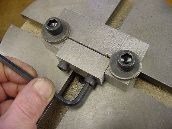
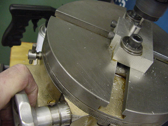
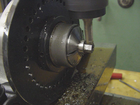
Here's where I spent some time thinking. I made up an aluminum clamping block and roughly centered it on my rotating x-y table. This old Craftsman tool is one of the very few items I inherited from my grandfather, who had been a real "Gyro Gearloose." |
|
|
So I stuck the rotating table on my mill, and proceeded to mill a hole in my little fixture, which I had clamped shut with a small spacer so it would tighten on the part afterward. |
|
|
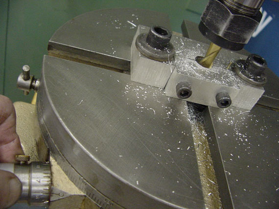
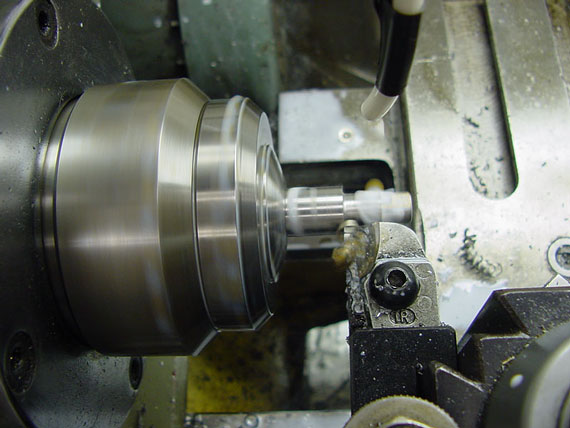
By moving the x-feed and rotating the table, I was able to generate a perfectly centered hole to clamp my new threaded part. |
|
|
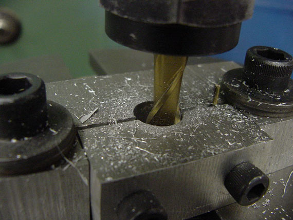
Then, with the x-y feeds locked and using the index marks on the rotating table, I was able to mill 7/64" holes down the side of the threaded portion to form the teeth of the die. |
|
|
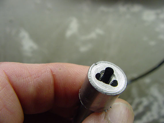
Here it is, up close. |
|
|
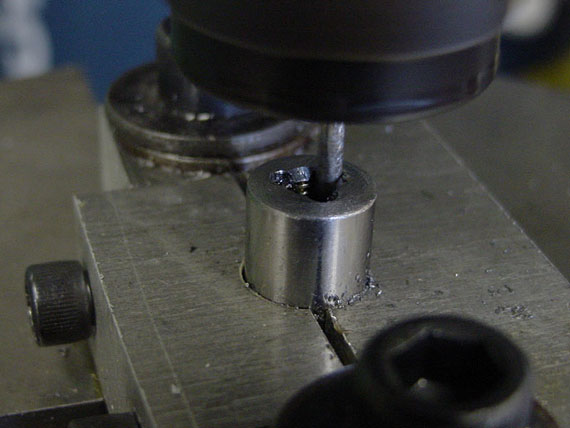
Then, off with that fixture, and on with my little cheapie Chinese spin index jig. |
|
|
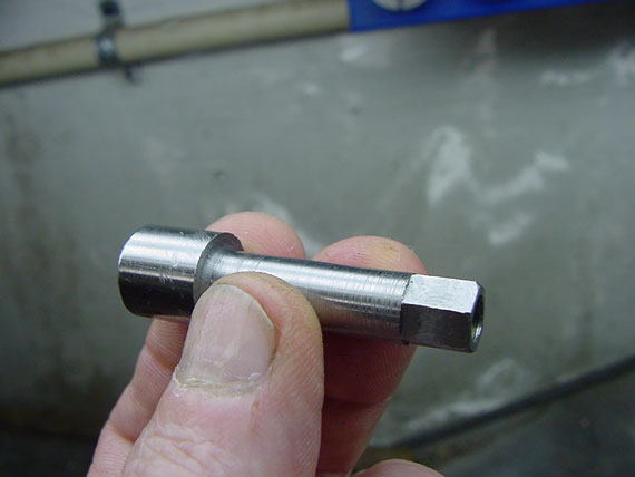
I milled 5/16" hex shank so it can be driven with the long StewMac Gibson truss rod wrench. |
|
|
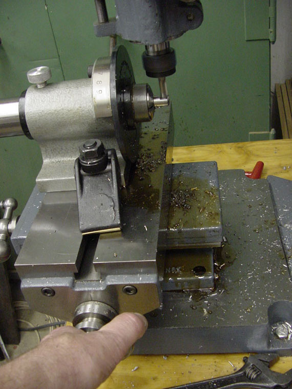
And, the final shot - turning down the shank to help clear the truss rod pocket and to make it a bit easier to align the tap. |
|
|
The end |
|
|
The side |