
Assembling the MLA Filing Machine Kit
Last month I received my new kit from Andy Lofquist at MLA. As with so many other things, this is a poor way to acquire a tool on the cheap. While the kit is only about a hundred bucks, there are lots of small bits to buy, so my cost probably ran to twice that in total, including UPS shipping, and extra bearing bronze I have leftover for another project.
But I was in the mood for a nice project, and this kit certainly presented that possibility, along with the bonus of a useful tool when completed. In fact, I learned a fair amount along the way. I'm sorry now that I didn't take photos of the kit pieces that consisted basically of four iron castings - the body, end plug, table and yoke. I think you'll be able to get a sense of how things were delivered as you view my process photos.
As I organized these photos, I realized that I hadn't exactly followed a direct path on each of the parts, so when you look at them you'll see that I bounce back and forth a bit in time. Andy had designed the instructions with the thought that you could do virtually all the machining with a 9" Southbend lathe, but since I have a good number of other tools, I used the setups that came most easily to mind, eventually using two lathes and two mills in the process.
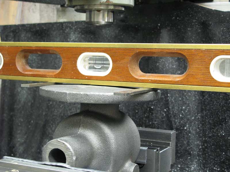
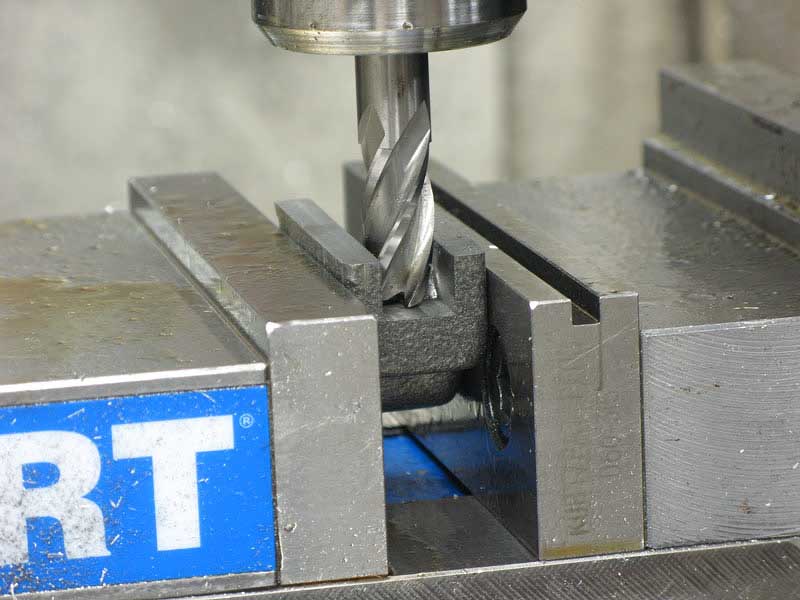
The main body casting was first on my list, and it needed to have a good reference surface, so I flattened the bottom on the mill. I spent a little time jockeying a standard carpenter level to get the casting approximately aligned with the mill table:
This kind of alignment is the reason I leveled the mill in the first place. All my future machining on the casting would reference to this flat surface.
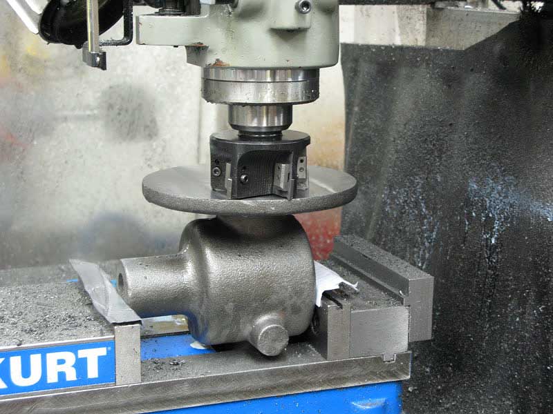
A few passes with my largest cutter, and I had a nice flat bottom:
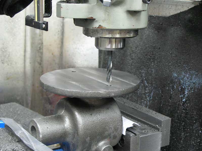
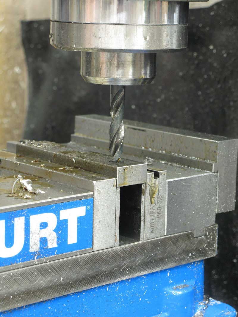
Two 5/16" mounting holes came next:
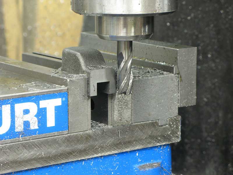
Turning the casting over, and gripping the bottom with the vise, aided by a couple of hold-downs, I milled the top face of the casting to the recommended height:
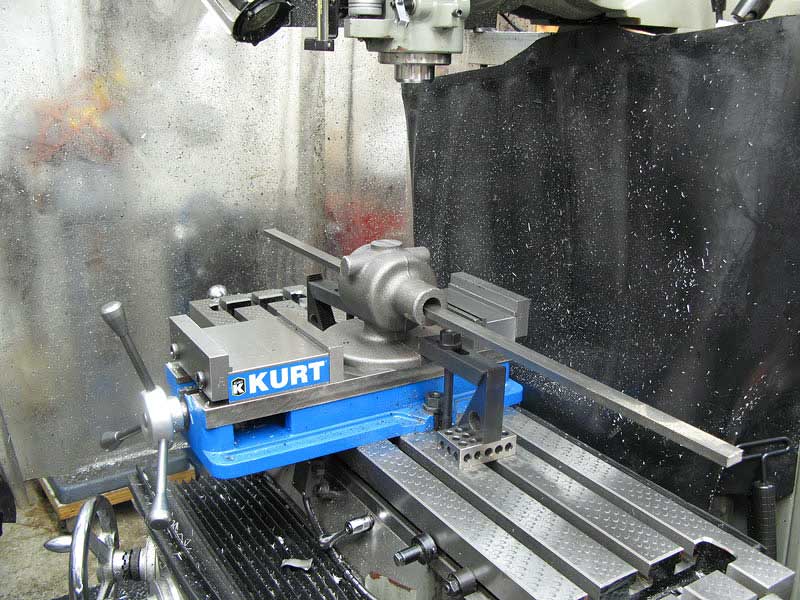
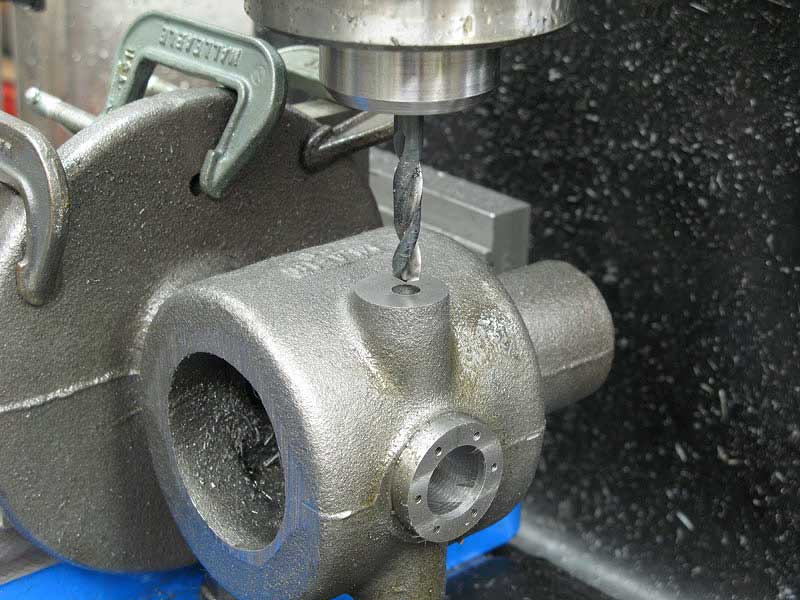
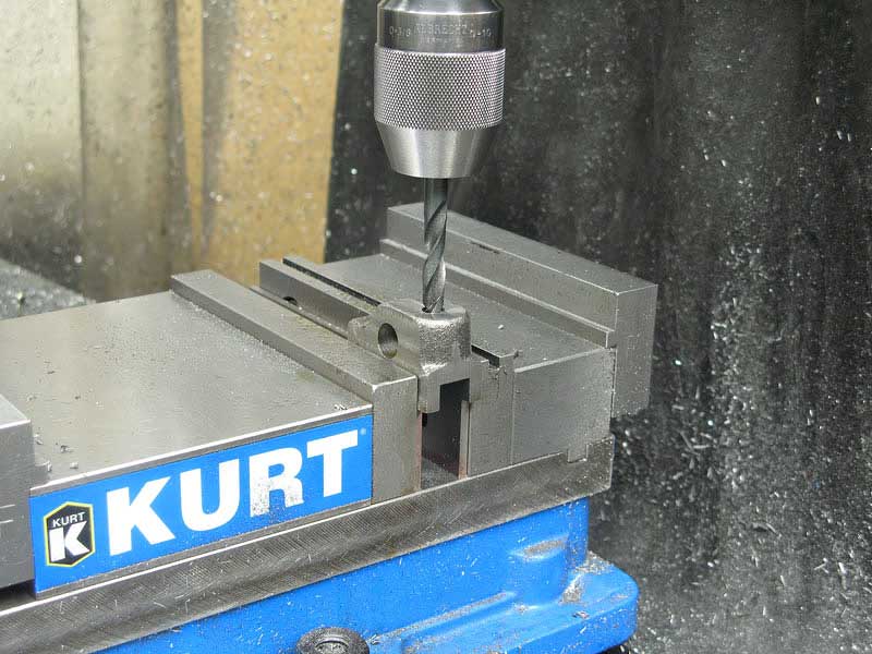
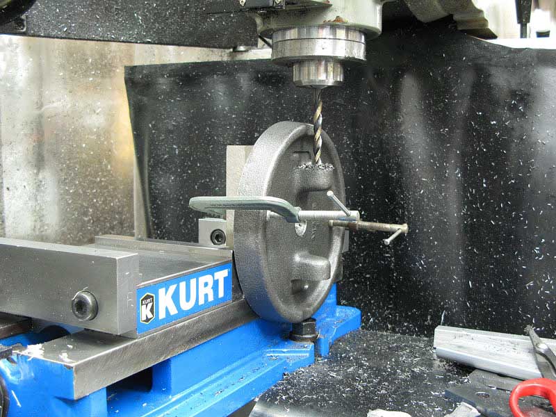
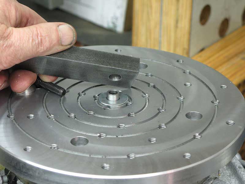
I'd want the table mounting bosses, drive bearing, and vertical bearings to be aligned as closely as possible, so I stuck a 1/2" square rod through the casting to help me eyeball it in alignment with the X-axis table:
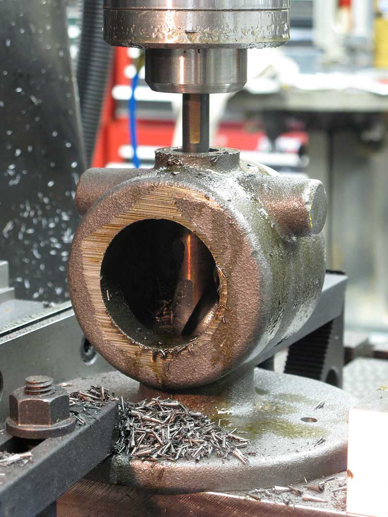
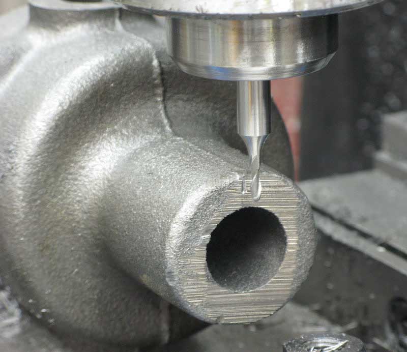
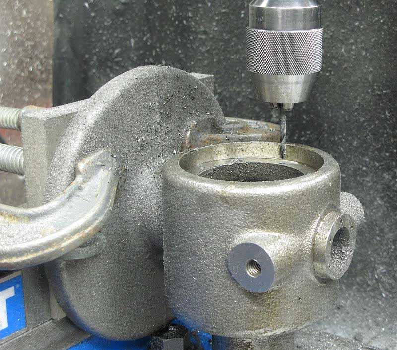
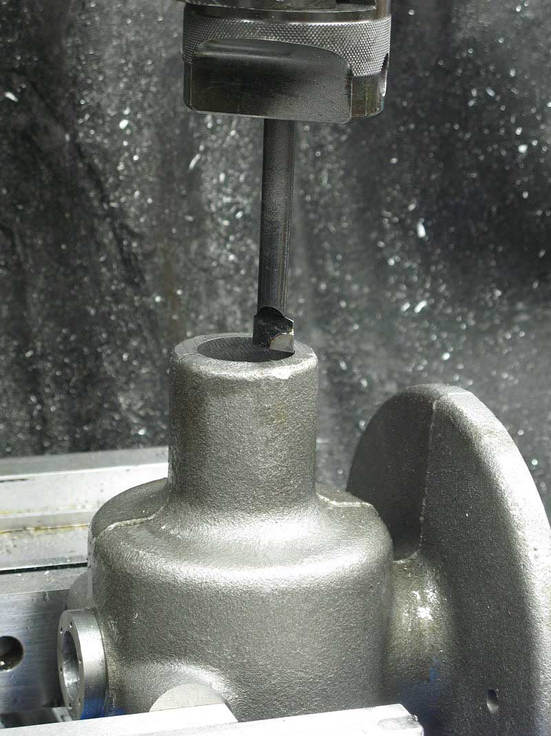
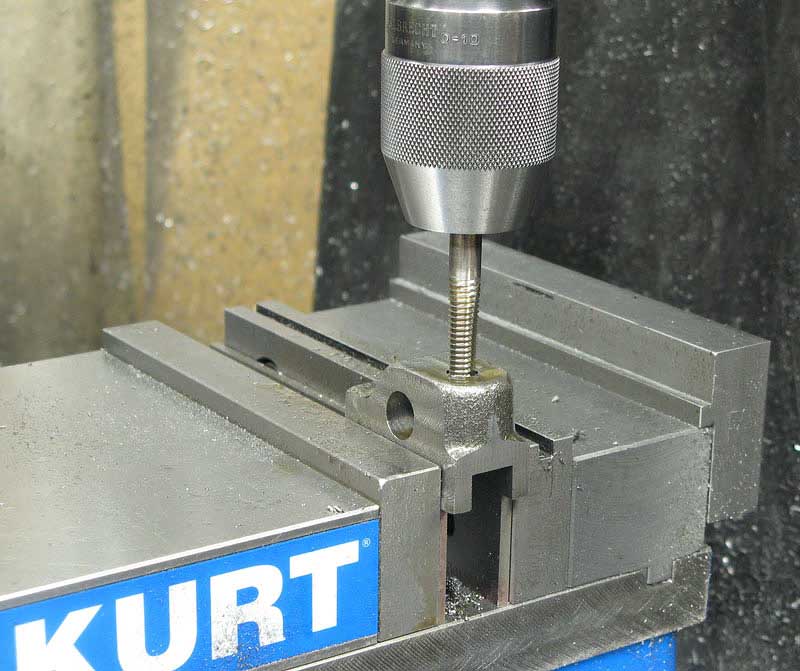
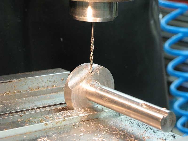
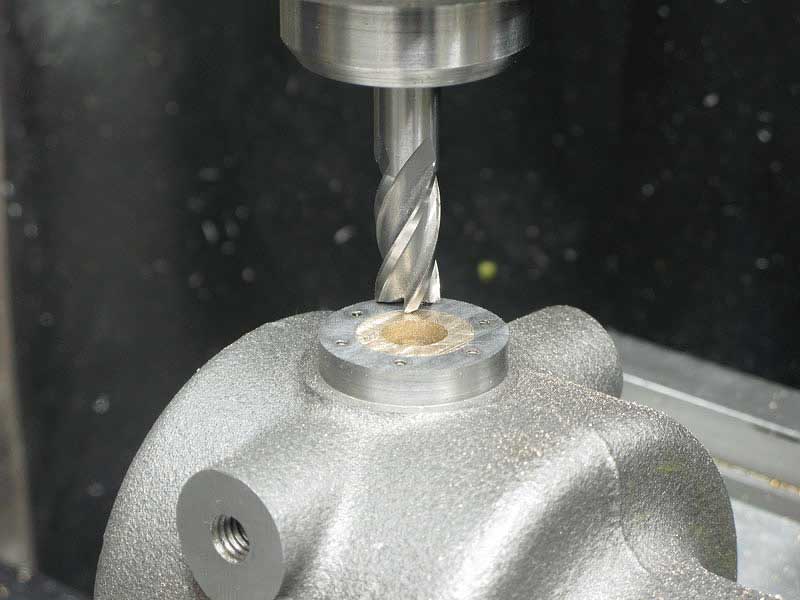
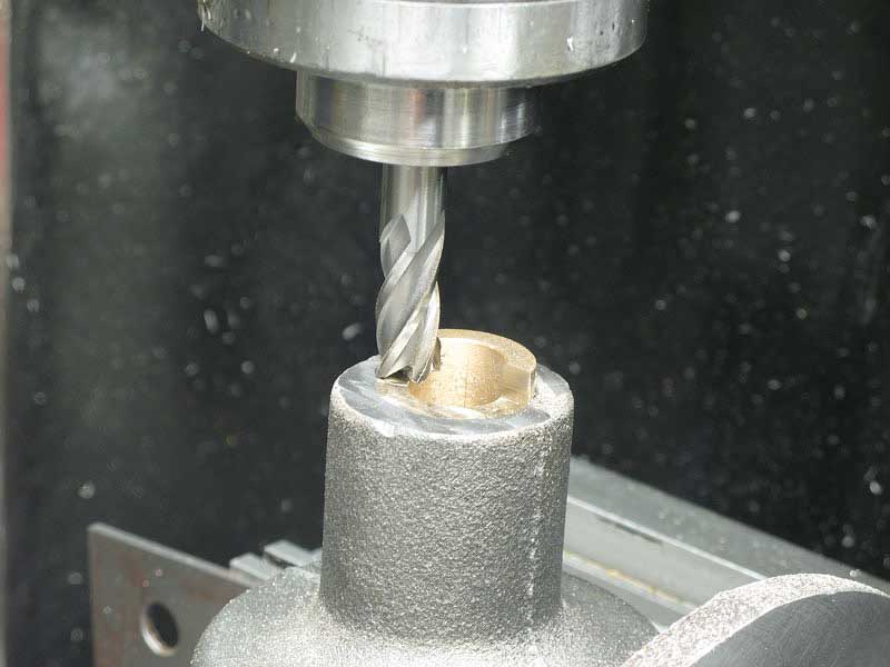
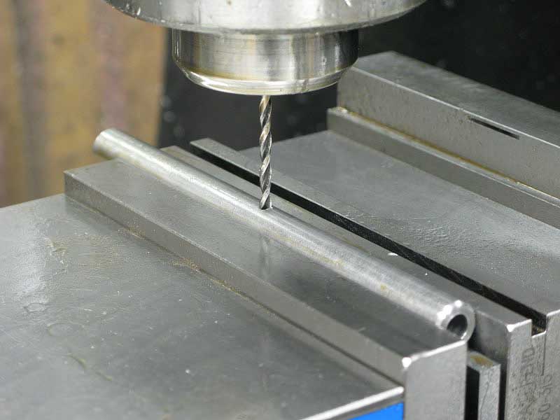
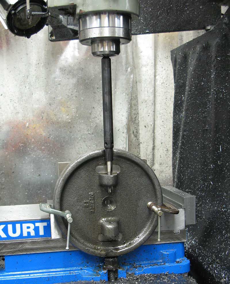
Once I had the casting clamped firmly in place, I was just able to drill through the vertical bearing hole with a 55/64" Silver and Deming drill:
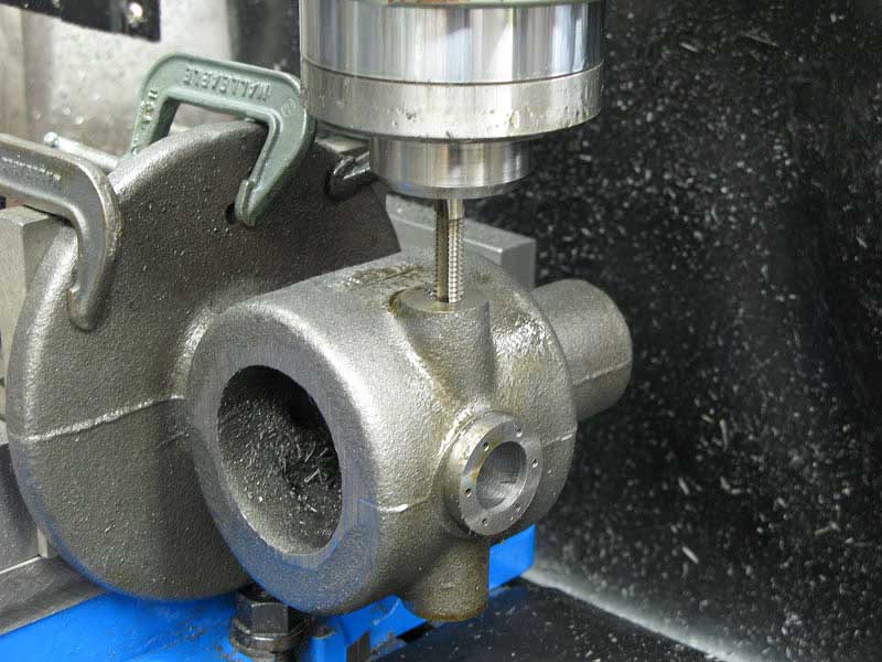
Following with a 7/8" reamer gave me a nice straight hole through both the top and bottom of the casting:
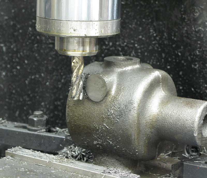
Without moving the setup, I milled the side bosses to receive the table mounting brackets:
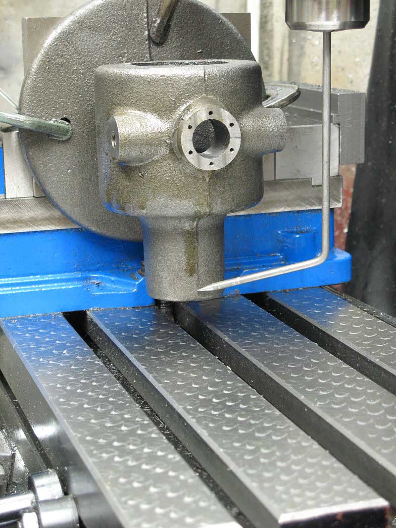
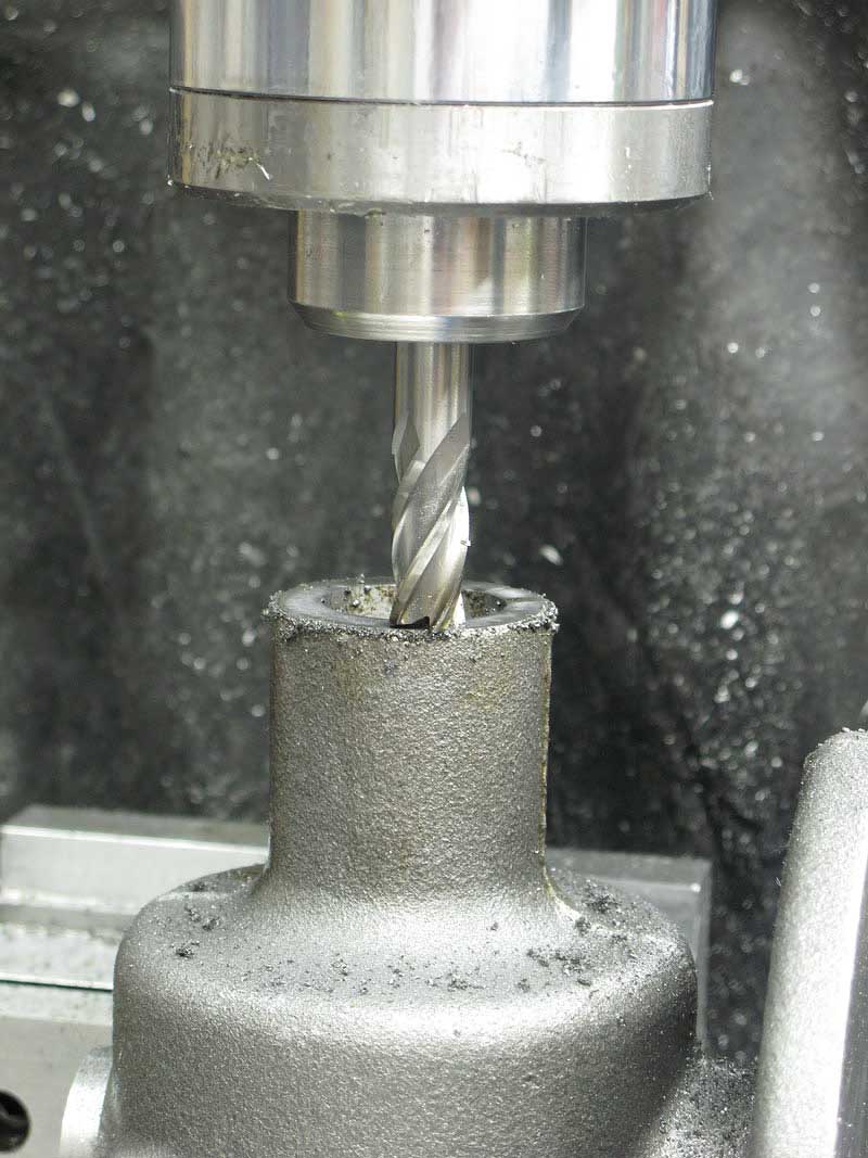
Here's my "creative" part. With the casting still aligned in place, I made some reference marks with a small ball end mill:
Marks on the table mounting bosses, each end and on top of the casting would allow me to align the casting for machining other features, keeping them parallel or perpendicular as required.
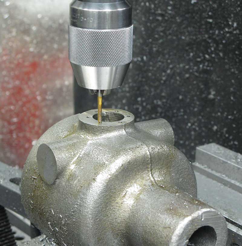
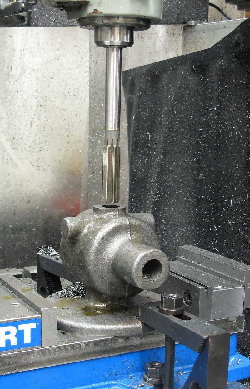
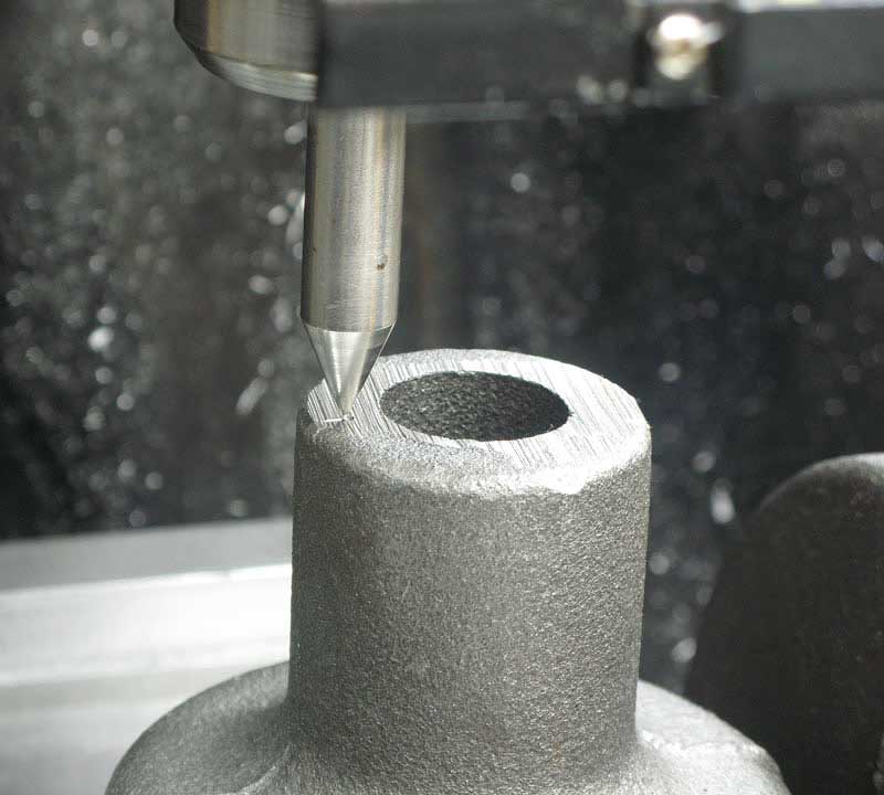
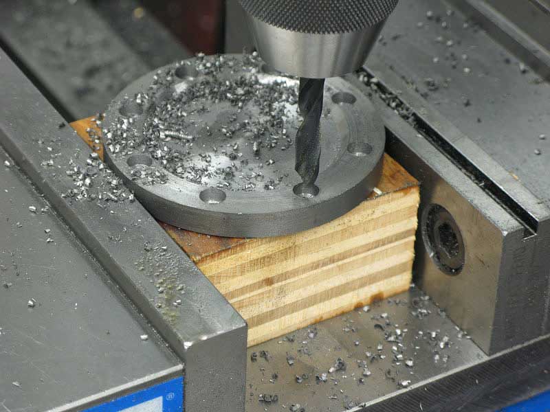
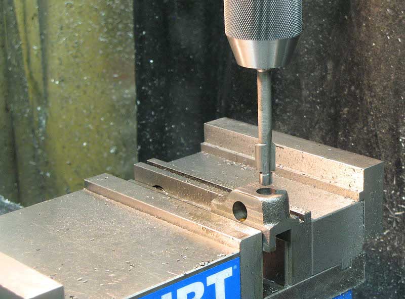
Back on top, I drilled and tapped the top boss using a standard bolt circle pattern and my DRO:
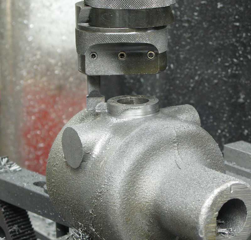
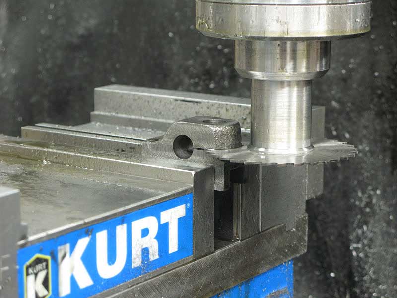
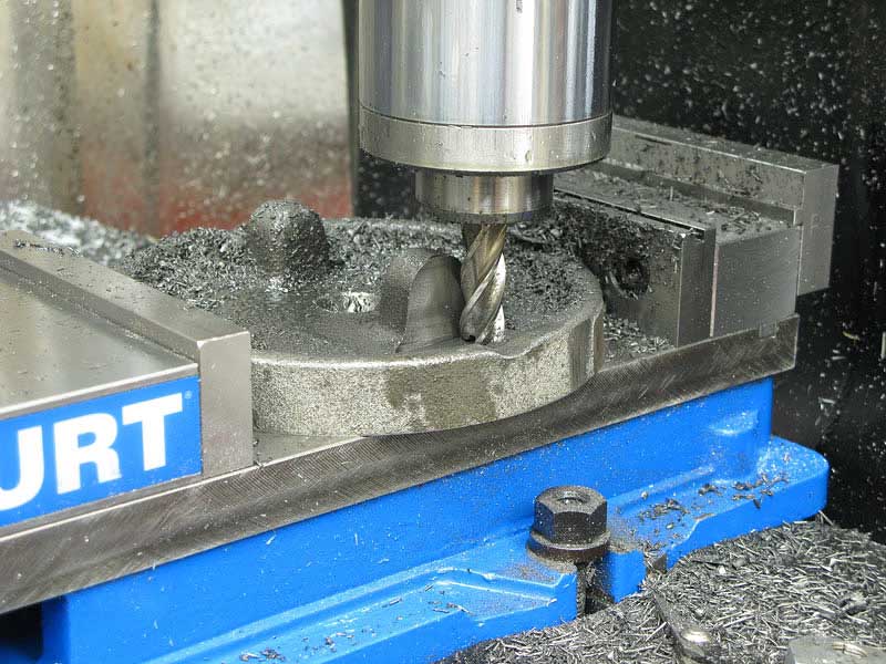
My boring head made quick work of rounding up that boss to accept the protective cap I'd be making later:
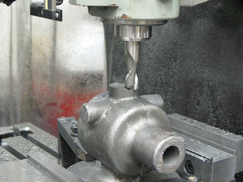
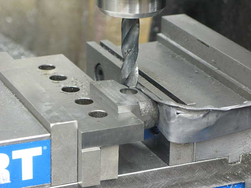
Now, with a big angle plate clamped in the vise, I was able to orient the casting using my reference marks so I would have the axis of the casting holes parallel to the table surface, but in line with the Y-axis:
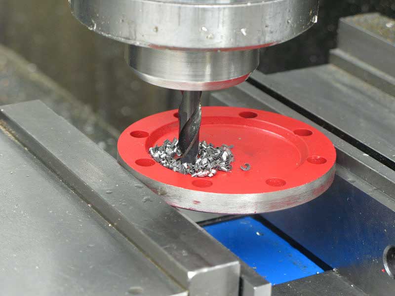
Using my reference mark on the boss, and the DRO to establish the distance from the angle plate, I could easily drill the holes in both sides with confidence that they would line right up:
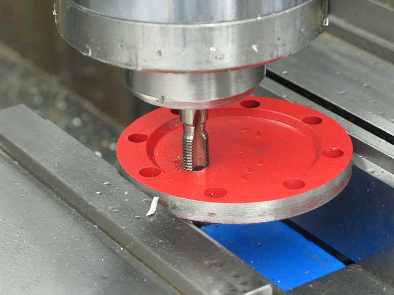
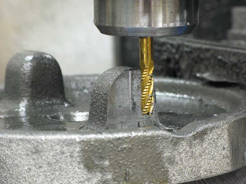
I tapped each hole right in the mill, using the back gear to slow it to 50 RPM:
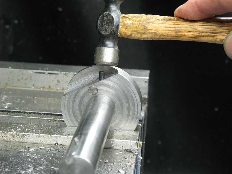
In order to rotate the casting as close to ninety degrees as I could, I used my reference marks and a simple pointer gripped in the mill collet:
It took a few minutes of tapping with a mallet, but I got the thing lined up pretty well.
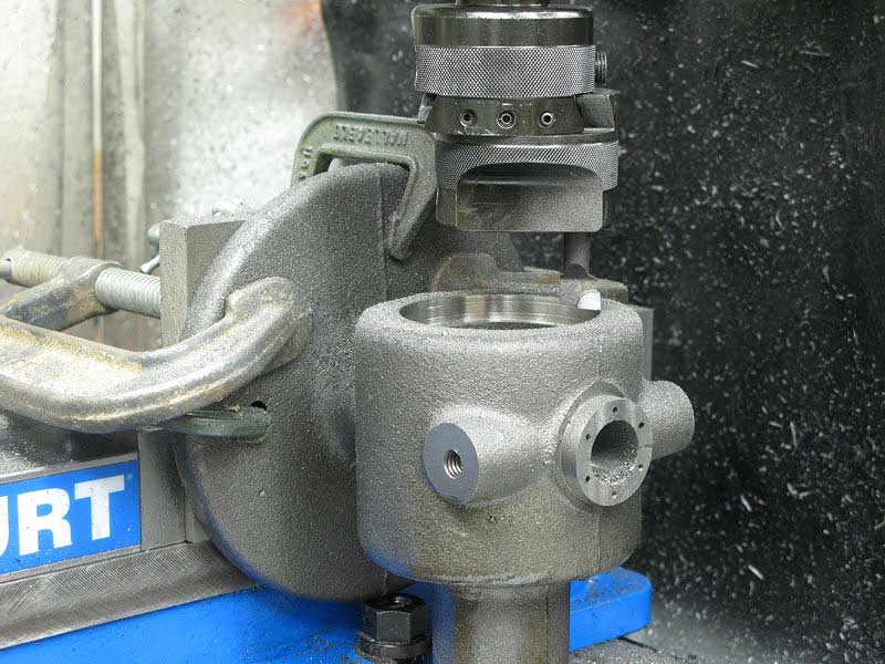
Back with the boring head to true up the recess for the end plug:
Using the bolt circle calculator again, I drilled eight holes:
And tapped them on the mill:
Because I'd need to turn the casting over to bore the hole for the drive bearing, I figured I'd want a good reference surfaces, so I milled the outer edge of the casting nice and flat:
I turned the casting over and clamped it in the vise, using the bottom of the vise as a reference surface for my newly milled portion of the casting, and the machined side bosses to grip. I figured that would hold everything in good alignment, and I made sure by checking with my indicator. It was within a couple of thousandths across the surface, so I was good to go:
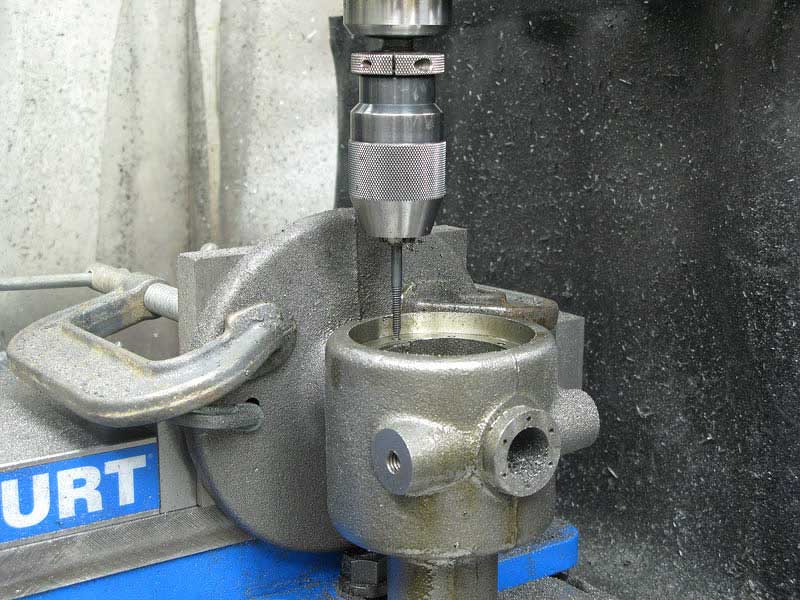
I used a simple pointer in the mill collet to line up with the horizontal center line I'd established earlier:
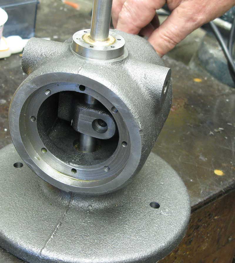
And, eyeballing the center on the other axis, I went to work with the boring head to make the hole 1.25" for the drive shaft bearing:
Just for neatness, I milled off the end of the casting:
Here's where we jump ahead for a quick diversion.
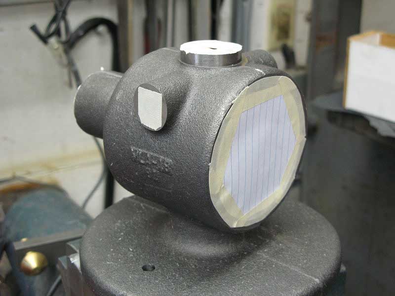
At this point I have the bearings installed, and figure it's time to paint. I masked off the obvious surfaces:
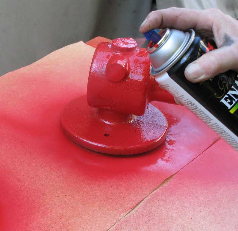
I chose red because I didn't (yet) have any red tools, and, of course, because I had some red spray paint:
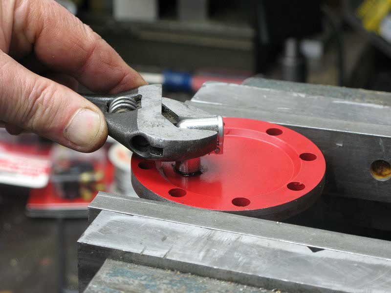
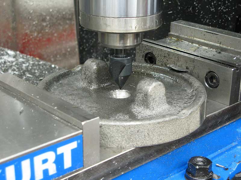
It was about then that I realized I hadn't countersunk the mounting holes. I would be screwing the casting down with a pair of 3/8" socket head cap screws, so I reached for my regular counterbore, only to find that there would be no way to clear the casting because its shank was way too short.
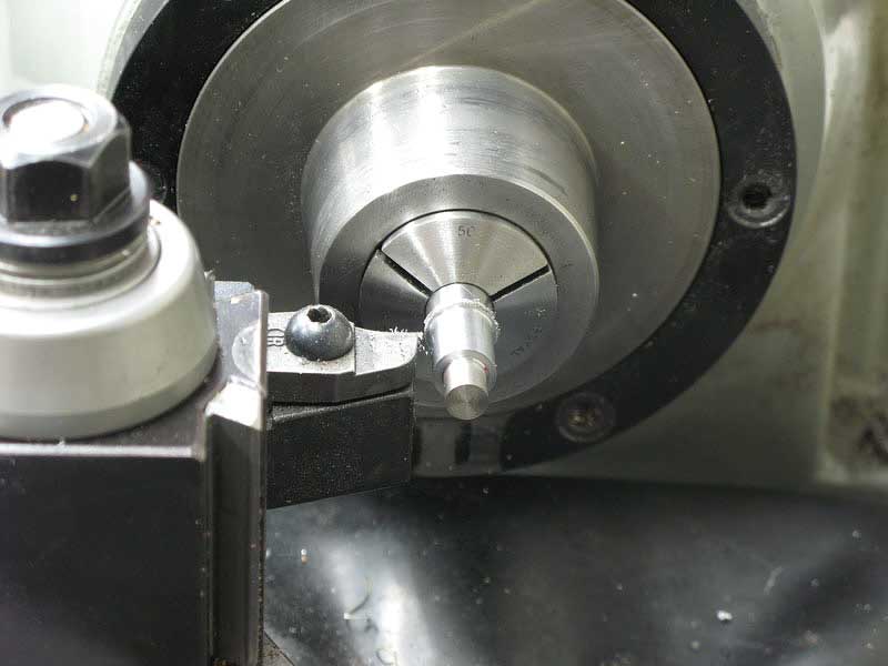
So, I set about making a counterbore for the job, first by turning the end of a piece of W-1 drill rod:
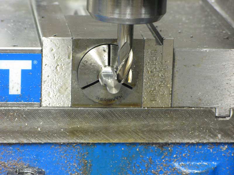
Then with the collet block in the mill vise I milled four cutting teeth on the end of my tool:
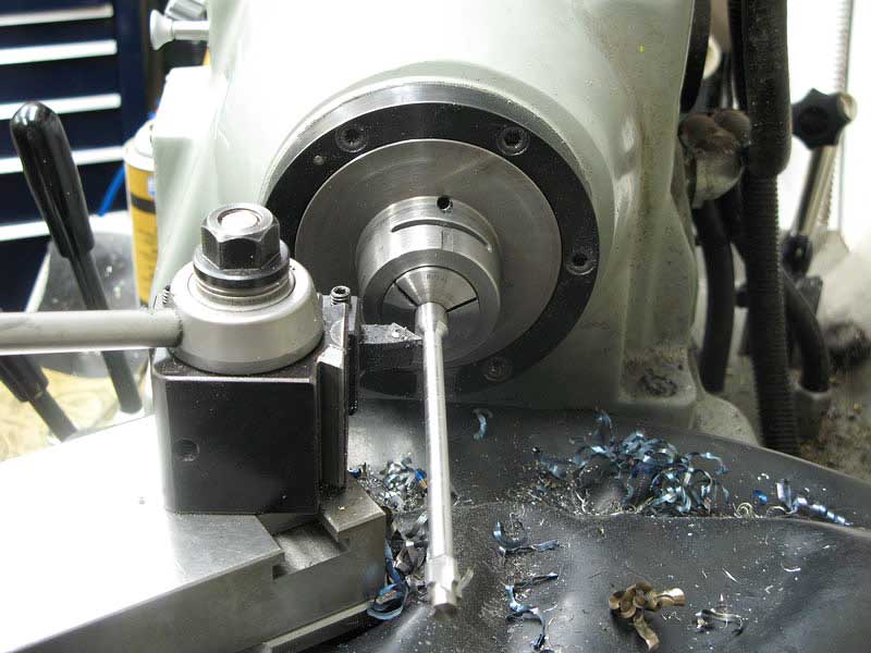
Even its 5/8" shank was too fat to clear the table mounting bosses on the casting, so I chucked it back in the lathe, and turned a section at a time down to 3/8" until I had enough length:
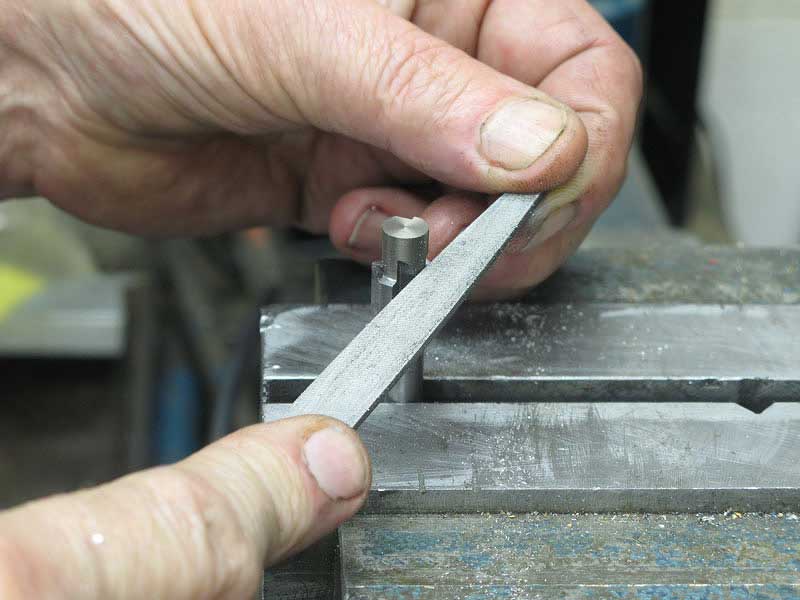
Next, I filed the teeth to nice sharp edges with some clearance:
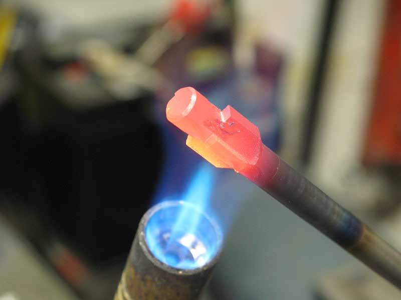
Got out the ol' propane torch and cooked it nice and red:
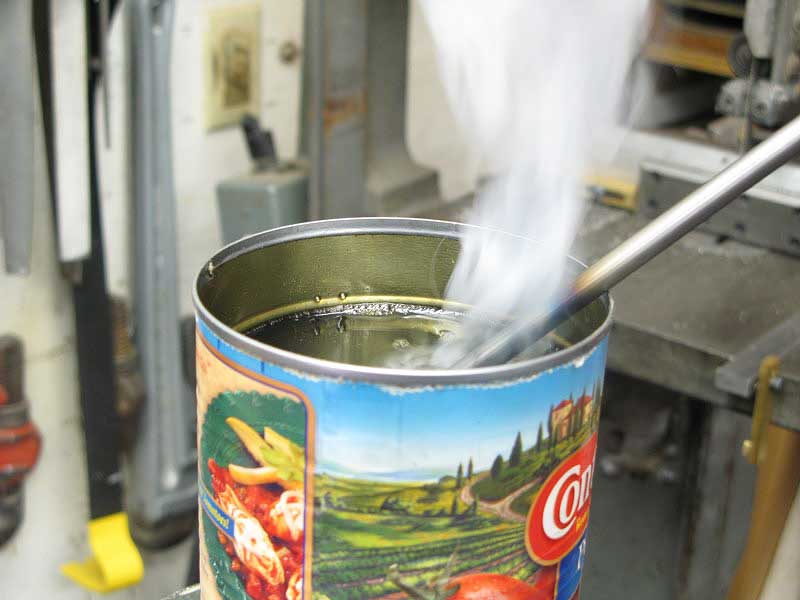
Plunged into a can of used motor oil, the water hardening rod didn't reach the full hardness it would have if I'd used water to quench, but this way I avoided the need to temper it before use:
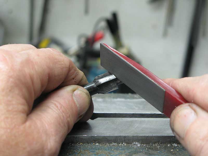
A quick touch with a diamond hone gave me a nice sharp tool:
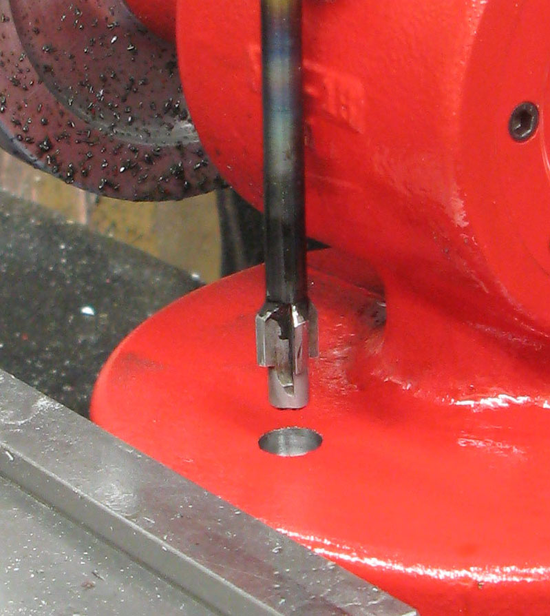
And, with its long shank, I was able to drill the casting without interference:
As you can see, I did this as the very last operation before mounting the tool to its board.
OK, back to the job in progress:
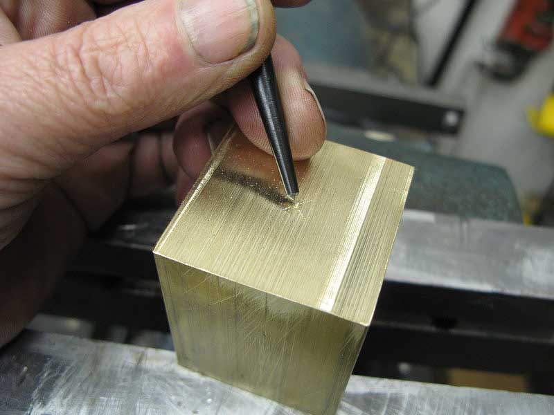
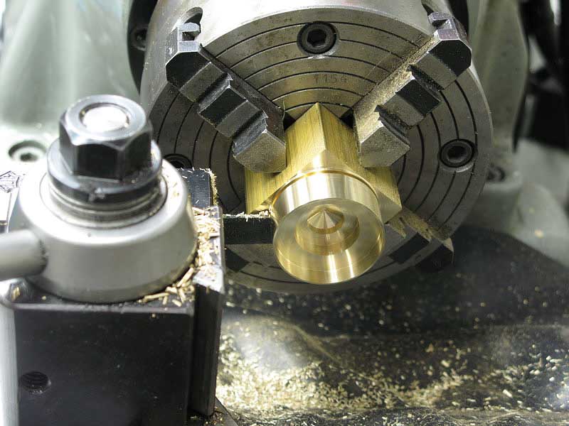
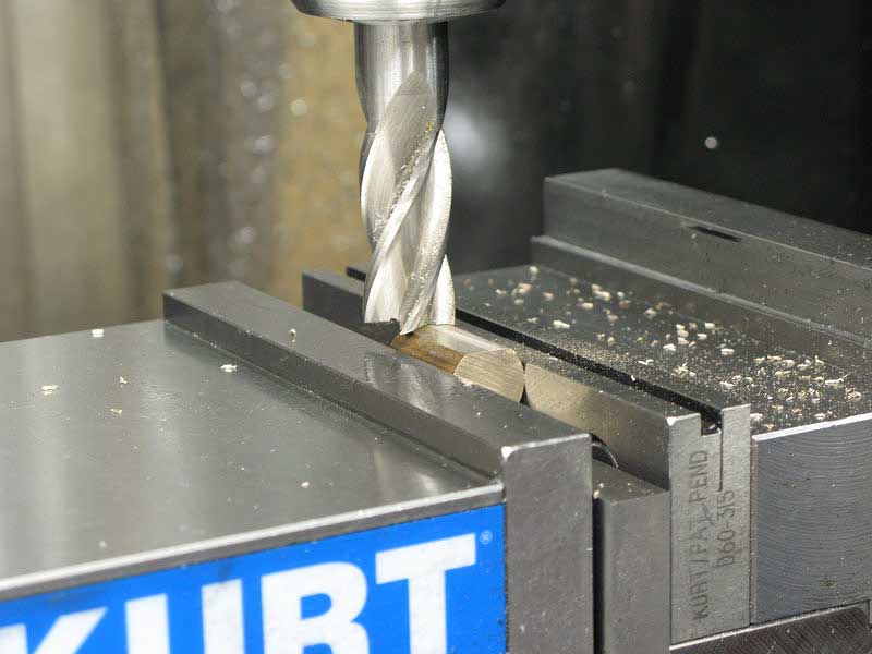
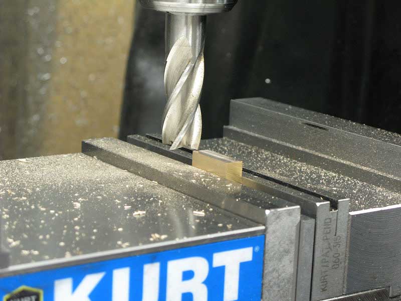
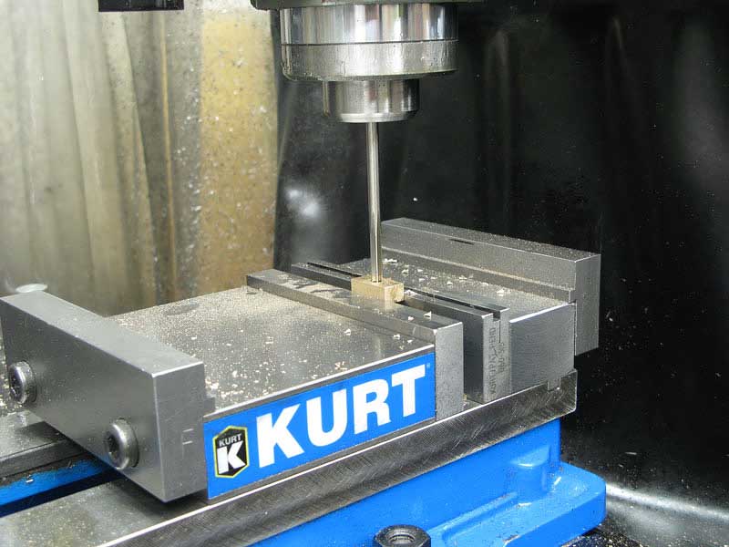
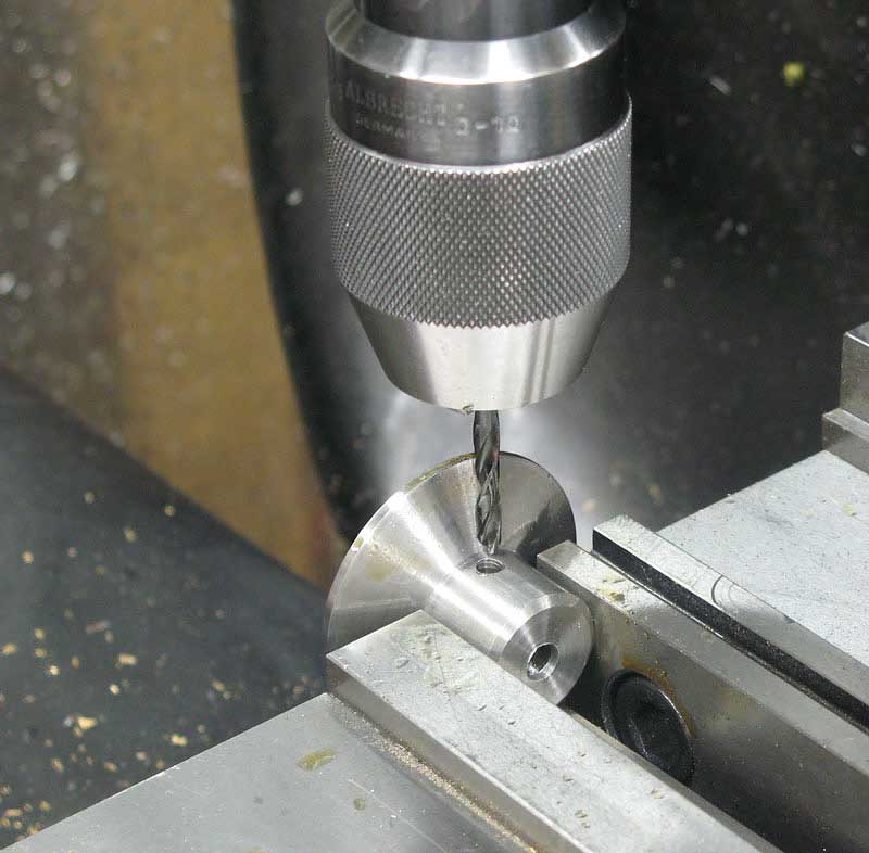
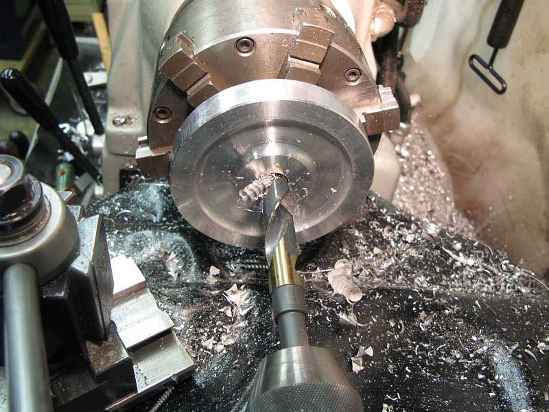
Looking around for material for the top cap, I found this nice hunk of brass, and marked its center:
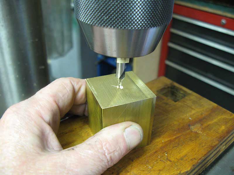
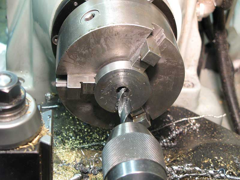
I center drilled it:
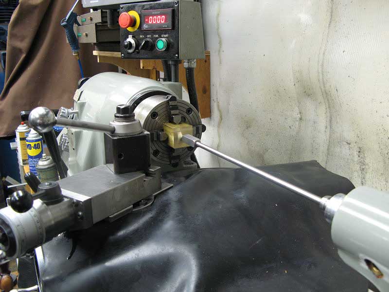
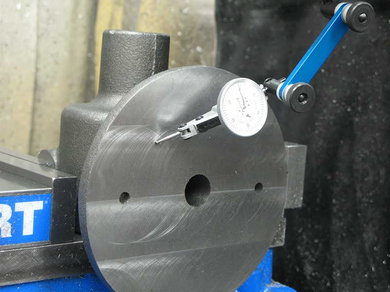
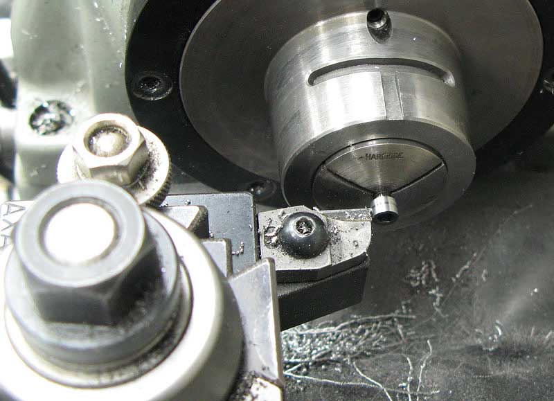
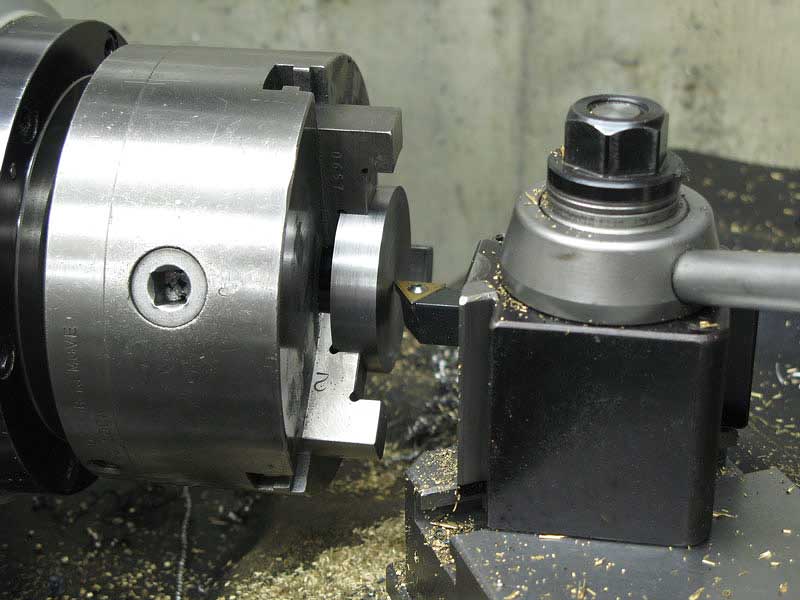
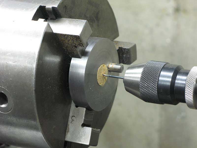
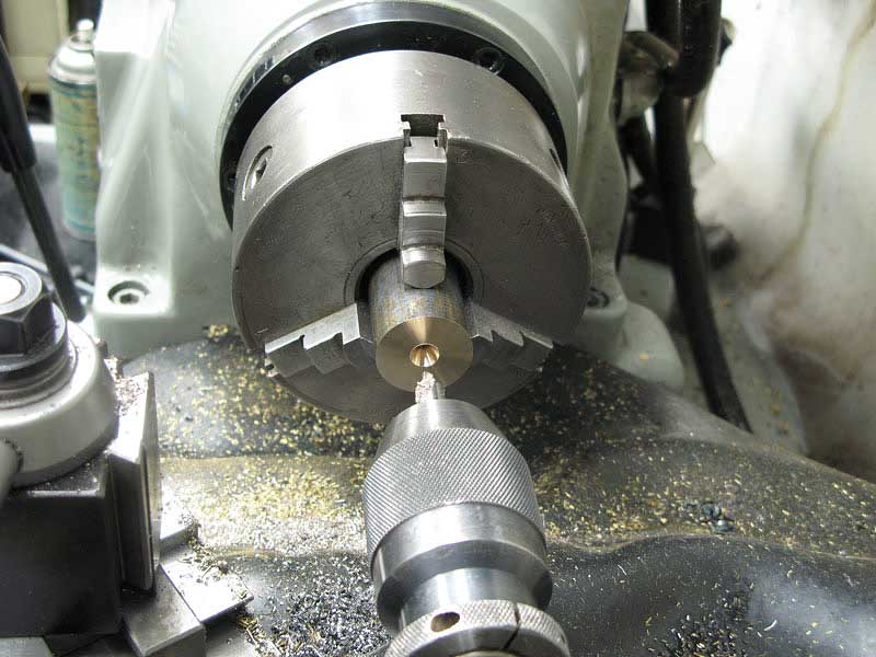
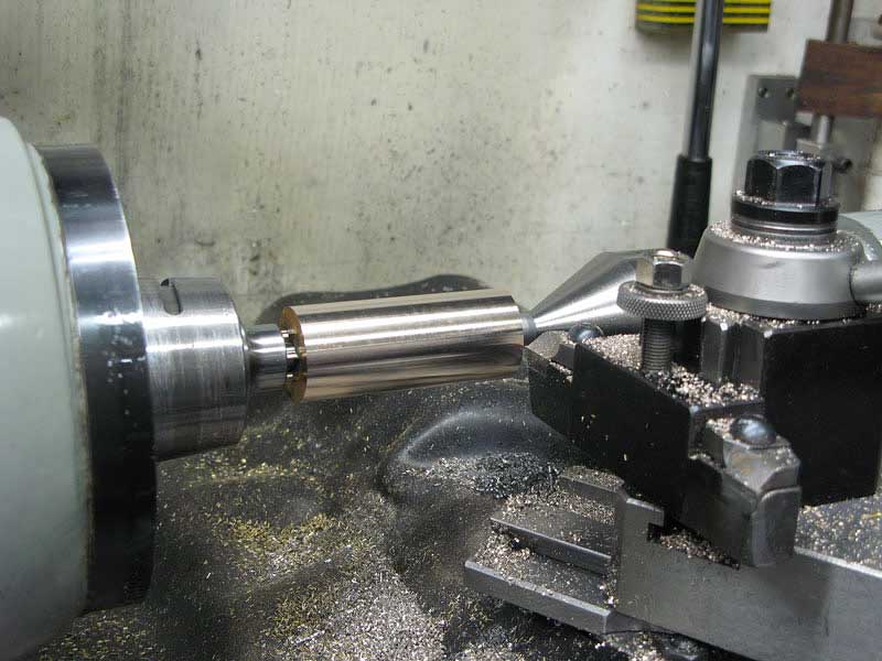
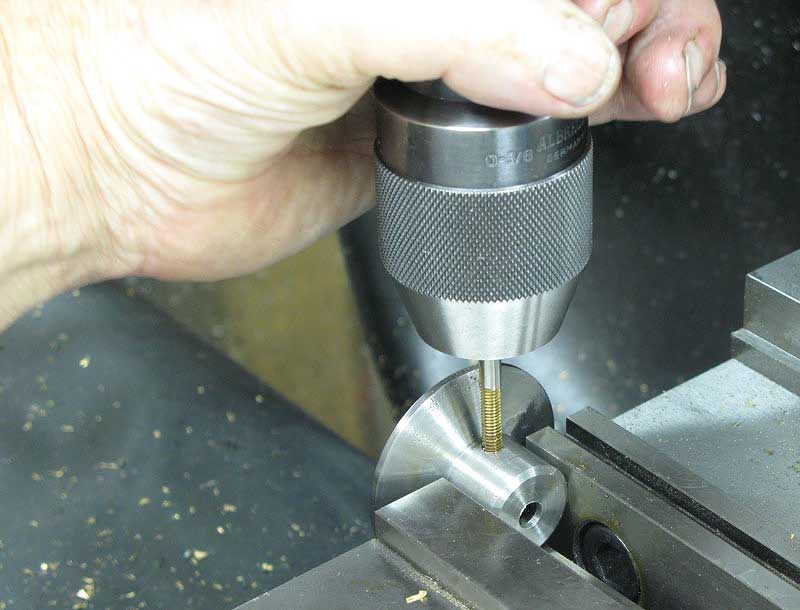
Once the piece was mounted in my four jaw chuck, I ran my long wiggly center right up to the center hole.
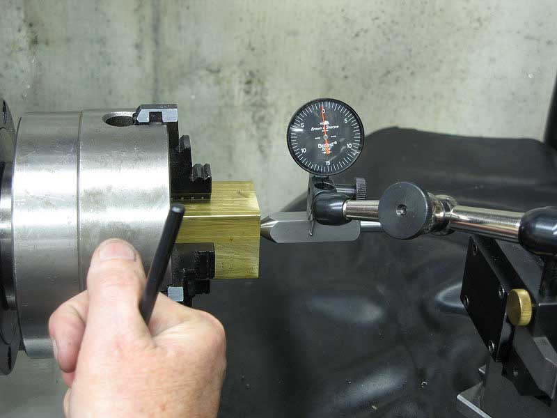
Centering is easy with this simple tool and a dial indicator:
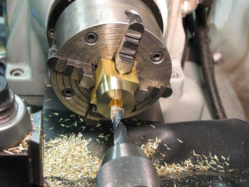
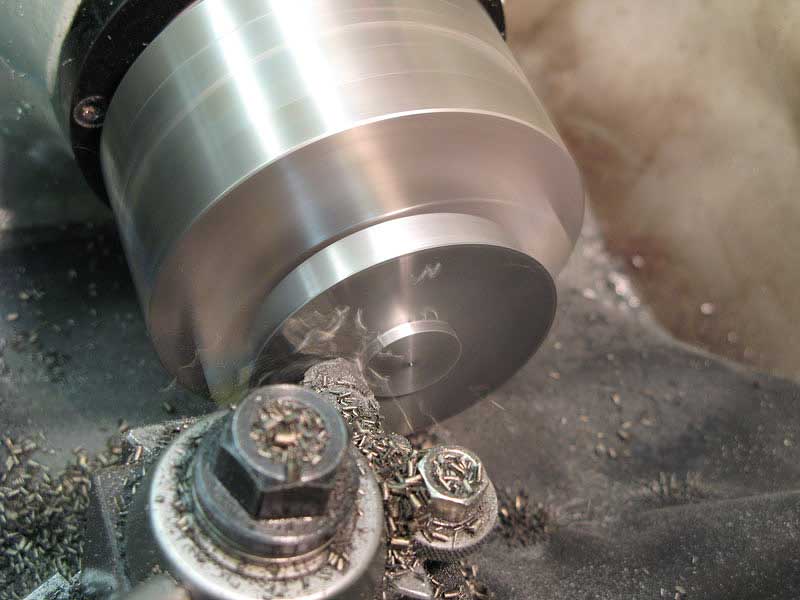
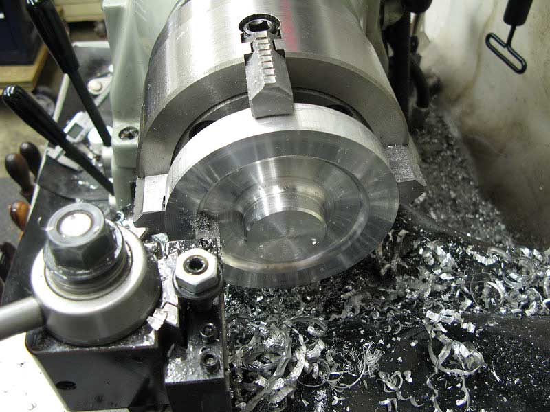
First, I rounded the section, and drilled through center:
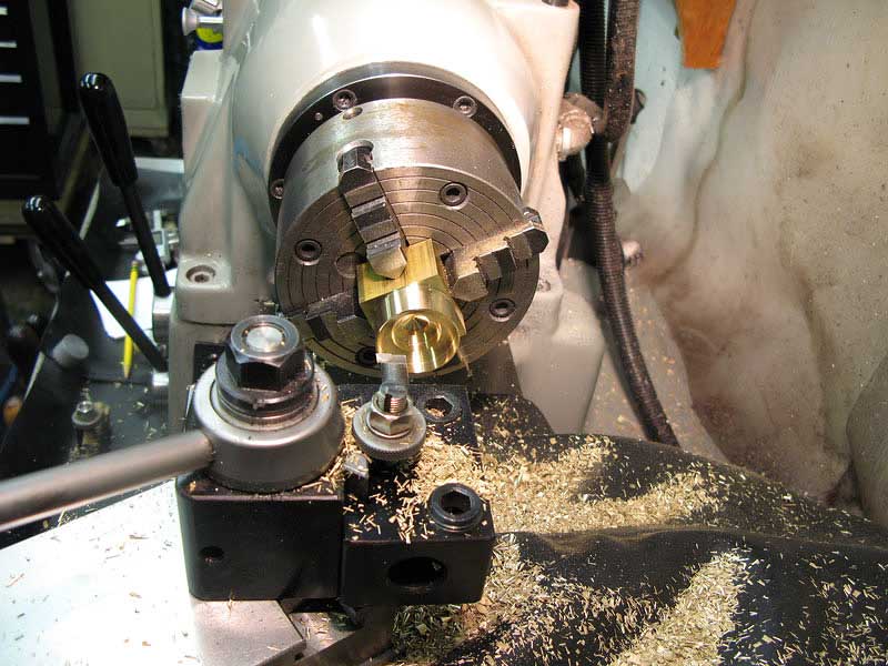
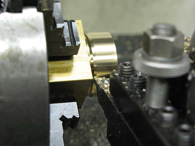
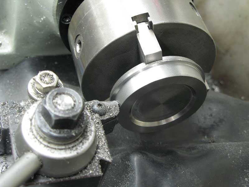
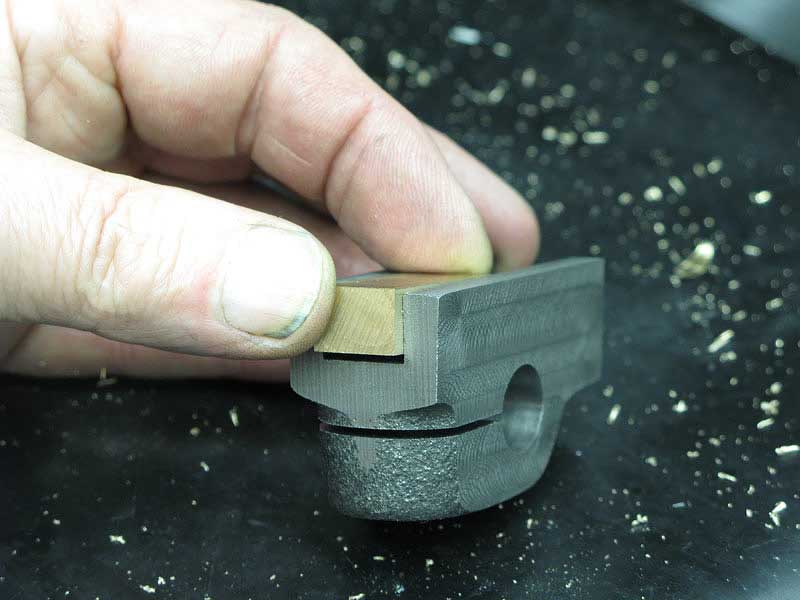
I bored out the cap to fit the boss on the top of the casting, and to receive the little felt packing washer:
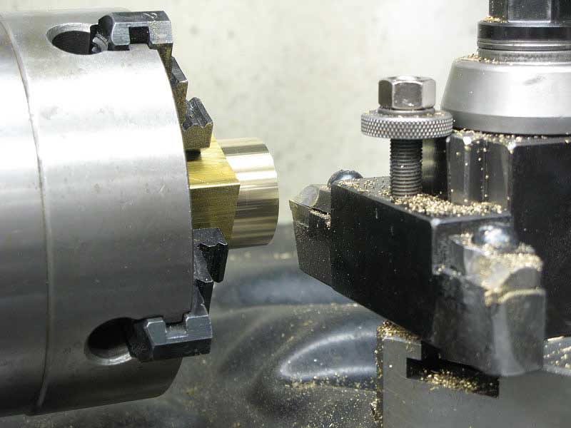
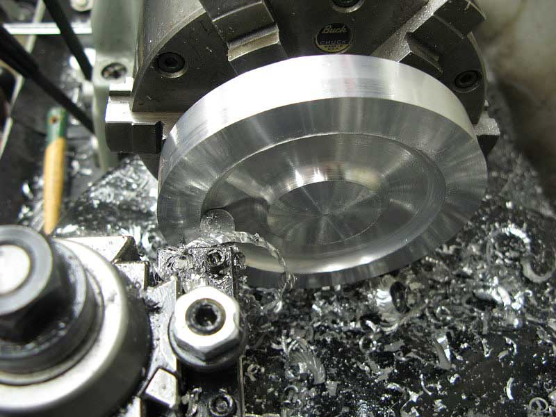
Then I cleaned up the outer edge:
And, started to part off:
Before finishing the parting cut, I switched to another tool to bevel the top edge of the cap:
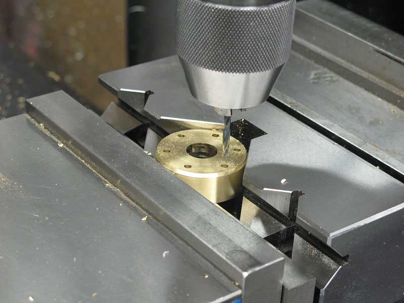
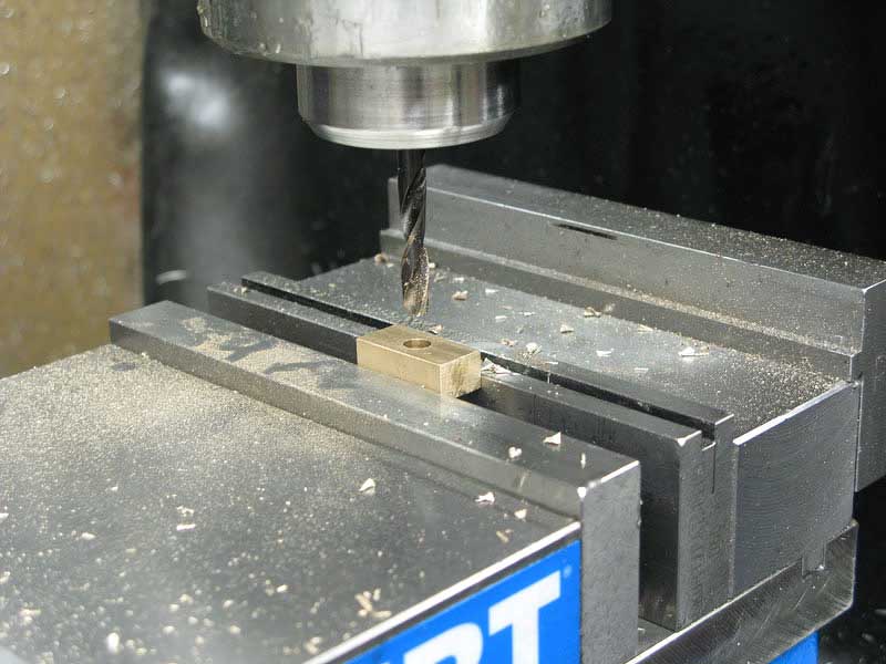
Using the same bolt circle pattern, I drilled the mounting holes:
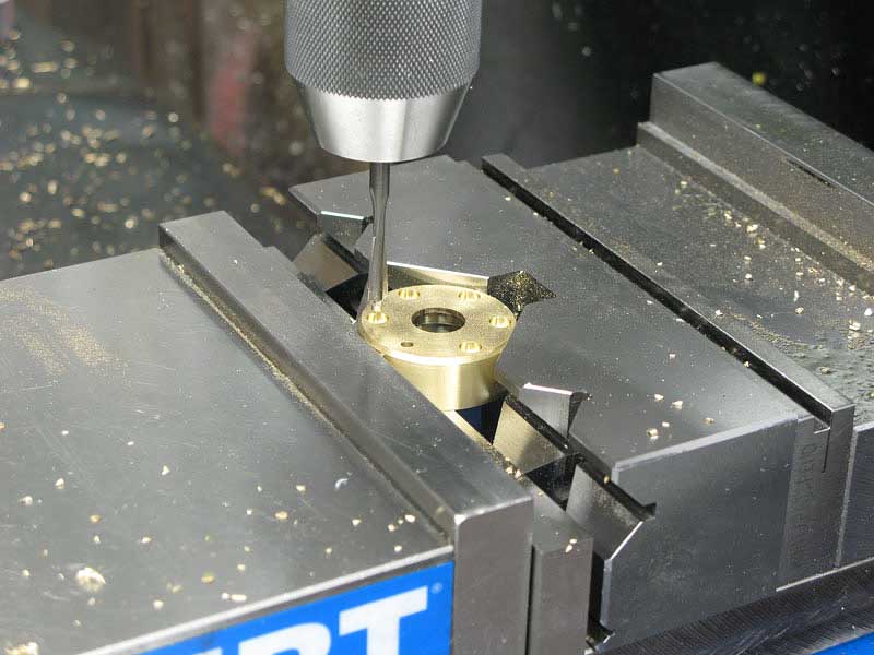
And, countersunk them for #4 socket head cap screws:
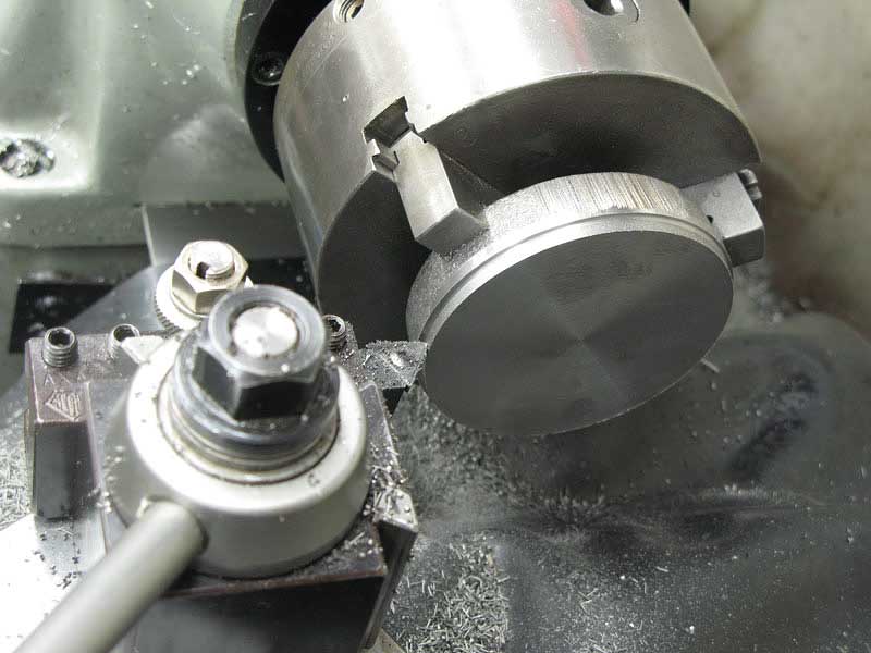
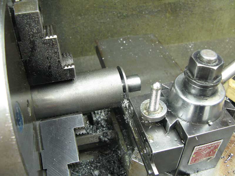
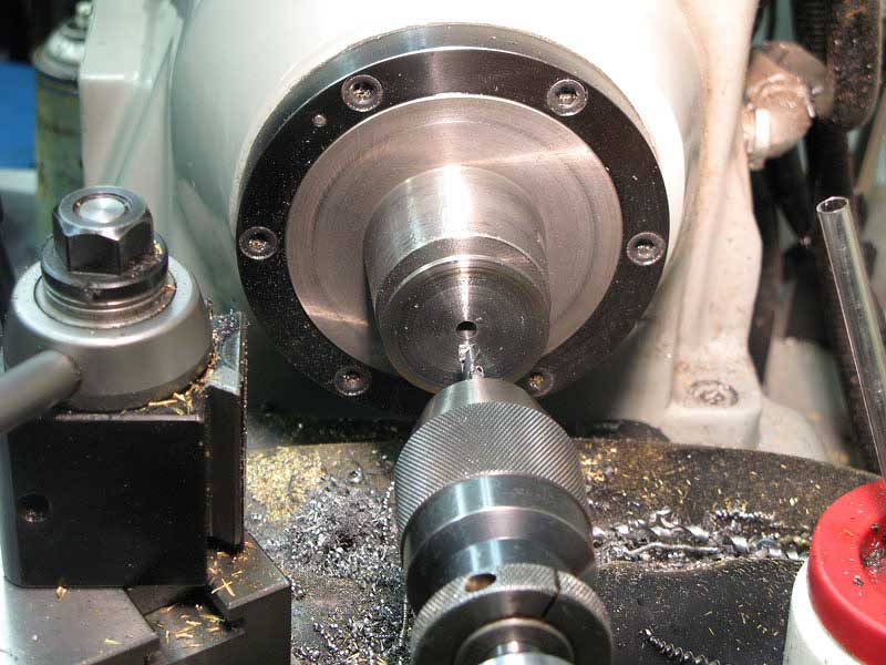
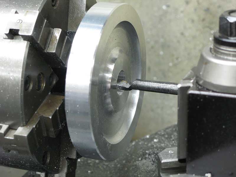
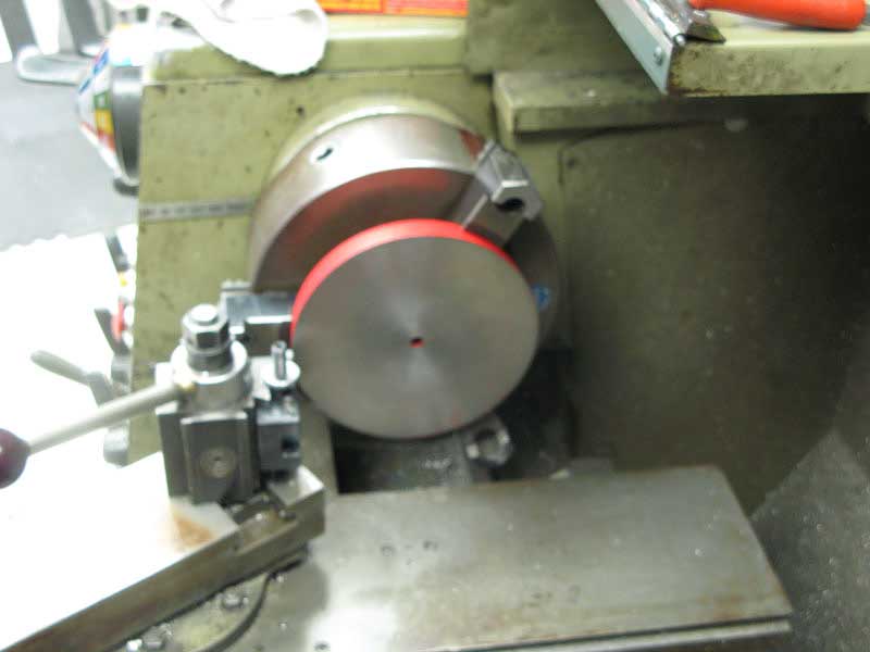
Here's the end plug casting, being turned to true up the back surface so it can be gripped in the vise jaws more securely:
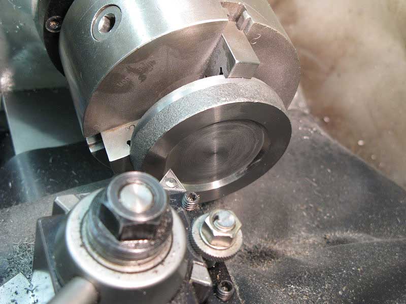
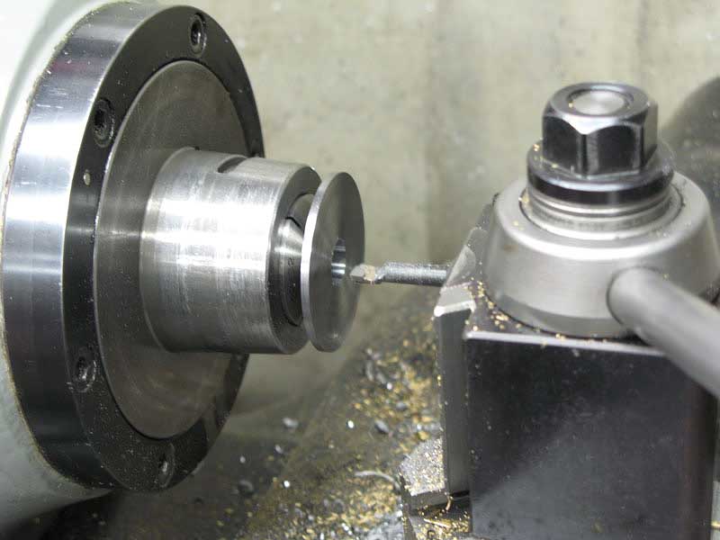
I turned the front recess of the plug to clean it up:
And, brought the diameter down to fit the hole in the body casting:
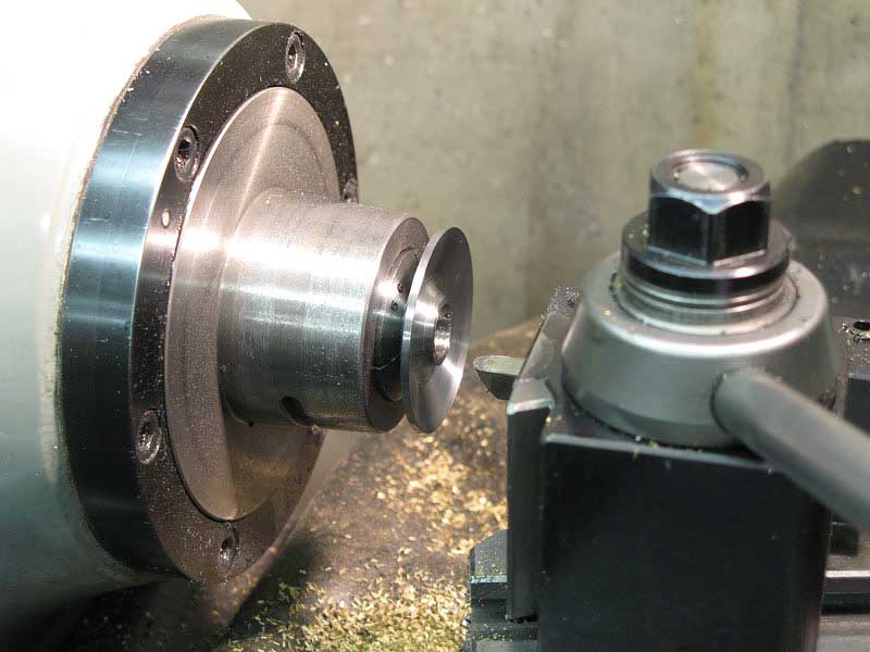
Turning the cap around again, I cut off the extra thickness from the back side so it would sit flush in the body casting:
Using the same bolt circle, I drilled and countersunk the eight screw holes:
Because clearance was tight, I needed to turn down the heads of the cap screws to fit my countersunk holes:
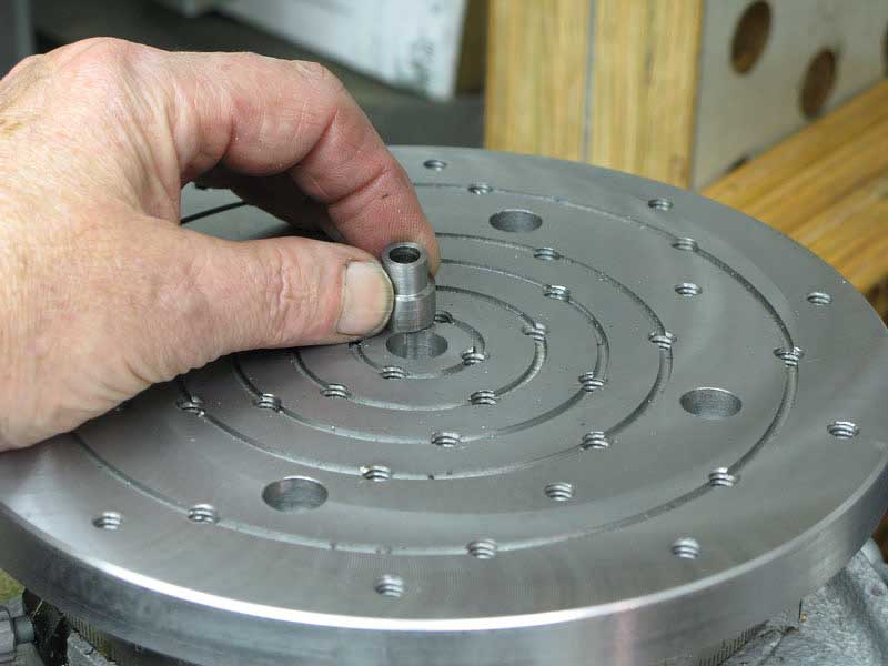
Here we go again, jumping ahead. Andy suggests that the oil level in the housing be maintained at a particular level but he doesn't provide an easy was to do that, so I thought I'd simply add an oil filler cup to the end plug.
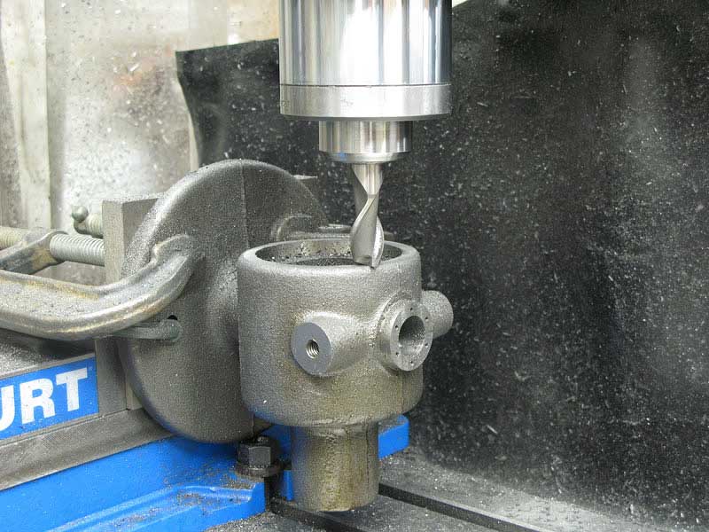
I drilled the plug:
And tapped 1/8"NPT:
The filler cap simply screwed in place:
Once I had the machine running, it was obvious that the pressure generated by the piston would tend to pump oil out of the filler cap, so I added a little breather hole near the top of the plug. You can see that hole in the final photos.
Now for the drive yoke.
I milled the casting for the slider:
And, milled both sides and ends of the yoke to clean them up a bit and make the yoke easier to grip in the mill vise:
Held with a bit of lead on the cast surface, I cross-drilled the yoke to accept the piston rod:
I drilled for the securing screw:
Tapped the hole:
And countersunk for the 5/16" socket head cap screw:
A 1/16" slitting blade did a nice job to finish off the yoke:
I made the slider out of bearing bronze. All I had was some round stock, so I gripped it in the vise and milled a flat:
Then I turned the piece, and milled the other three flat faces:
After a bit of trial and error, I got a nice flush, sliding fit:
I drilled the piece:
And reamed it to 1/4" for the dowel pin that would connect it to the crank:
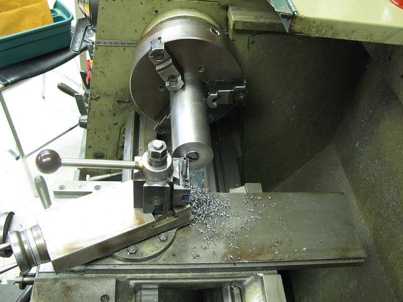
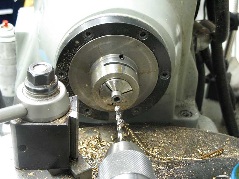
Speaking of the crank, it was to be made of steel, and something over 2" in diameter. I had a nice piece of 3" cold rolled steel rod, but I didn't want to waste a bunch of it cutting the end off and mounting it on my lathe. So I took a trip over to the TechShop where I could use their nice fifteen-inch Clausing Colchester lathe. Bending the rules just a bit, I faced off the end of the rod, with too much hanging outboard from the chuck. I took it slow and easy for safety:
I center drilled the rod:
With the work well supported, I hogged off a bunch of diameter to produce the disc I needed:
Now, wasn't about to try to part off the piece at that distance from the chuck without support, and I do know enough not to do it with a center in place. So, I cut through about two thirds of the diameter with the parting tool:
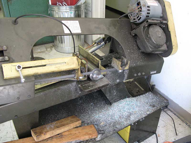
Then, I took the piece over to the horizontal band saw to chop through the last bit:
Back home, I cleaned up the faces of the disc:
And drilled the center:
I bored to 5/8" for the drive shaft:
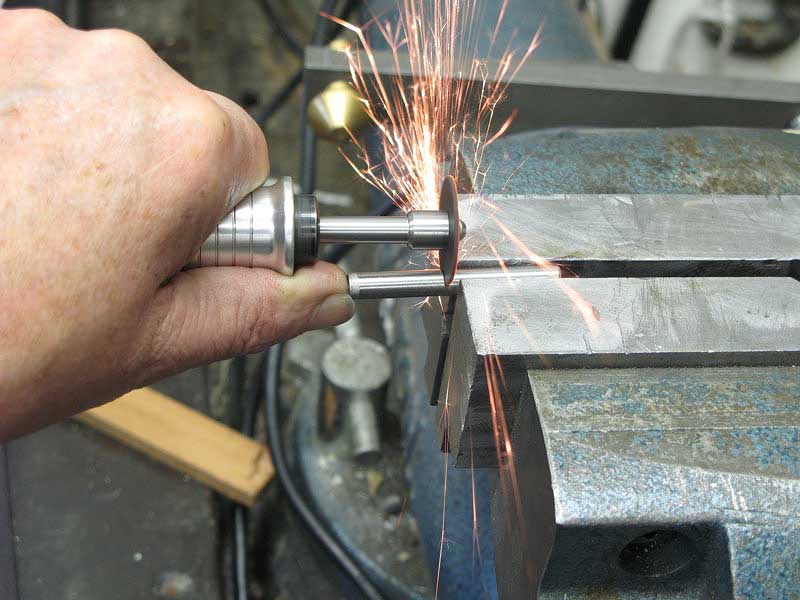
The little drive pin that connects the bronze slider is a one-inch long hardened 1/4" dowel pin. I had a two-inch pin, so I cut it with a carbide wheel on my Foredom:
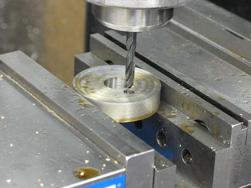
I drilled the crank disc:
And reamed it for a press fit (.249).
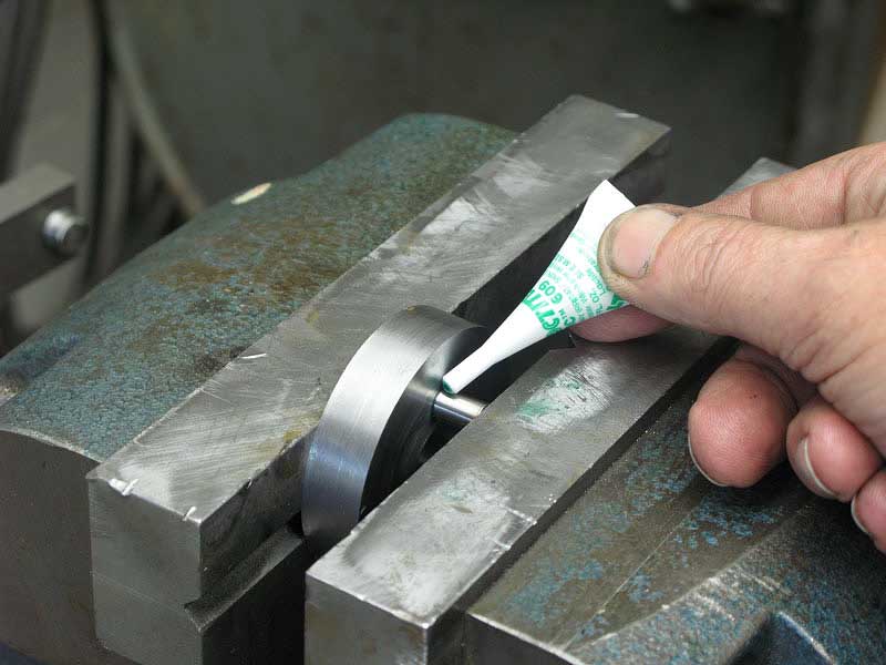
A bit of green Loctite and a good strong shove, and my pin was seated in there "for the duration:"
Andy's instructions contain a line or two about balancing the crank wheel, so I thought it would be a fun addition to my project, and set about doing just that, not realizing that the mass of the rod, file and mounting hardware was so great as to obviate this step entirely.
But, I did it, so I thought I'd show it. I took an old wine cork, sanded it down a bit, and crammed it into the hole in the crank disc. Then I drilled through on center 1/16" to insert a balance pin:
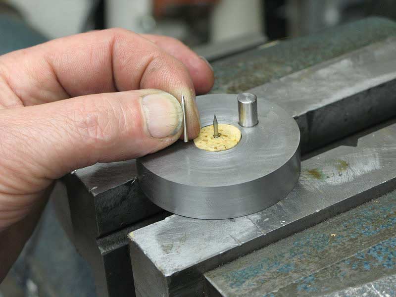
From a former life, I have a large supply of old hard steel phonograph needles. I stuck one in from each side of the cork, and glued them in place with a bit of cyanoacrylate:
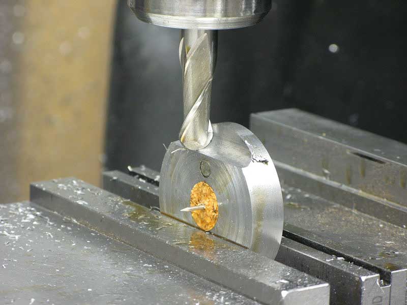
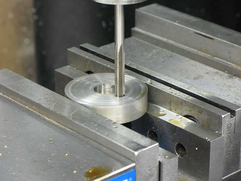
Then, I proceeded to mill off a section of the disc from the side opposite the 1/4" pin:
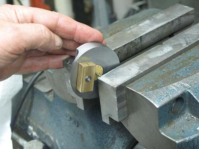
It was easy enough to set the wheel back on my vise with the bronze slider in place, and test the balance:
A few trips to the mill and I had it balanced rather well, I think.
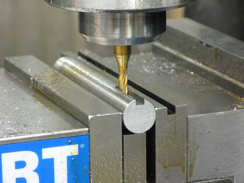
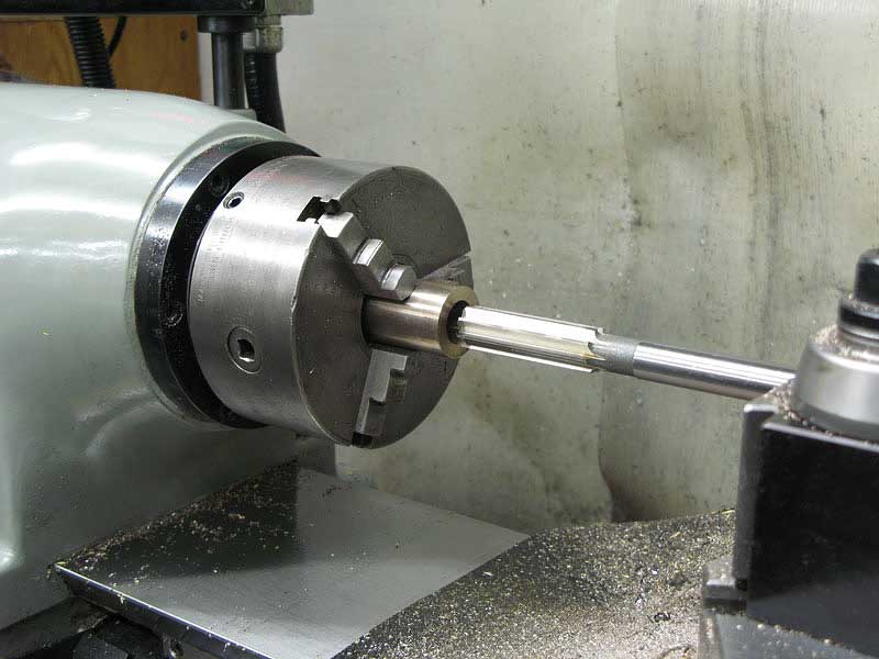
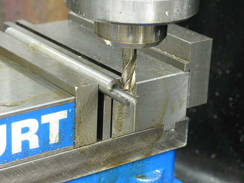
This is the drive shaft, a simple piece of 3/4" drill rod. I milled a 3/16" keyway in the shaft for the pulley:
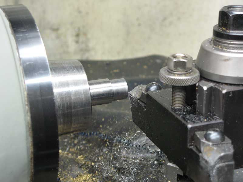
And turned down the other end to be a nice fit for the crank disc:
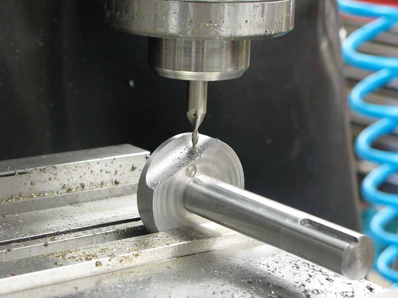
After pressing the disc on with some green Loctite, I spotted a place to drill for a pin. A quick touch with a 1/8" end mill gave me a flat land to drill through:
I drilled through the center with a 3/32" bit:
A few gentle taps seated a spring roll pin to finish the installation of the crank disc:
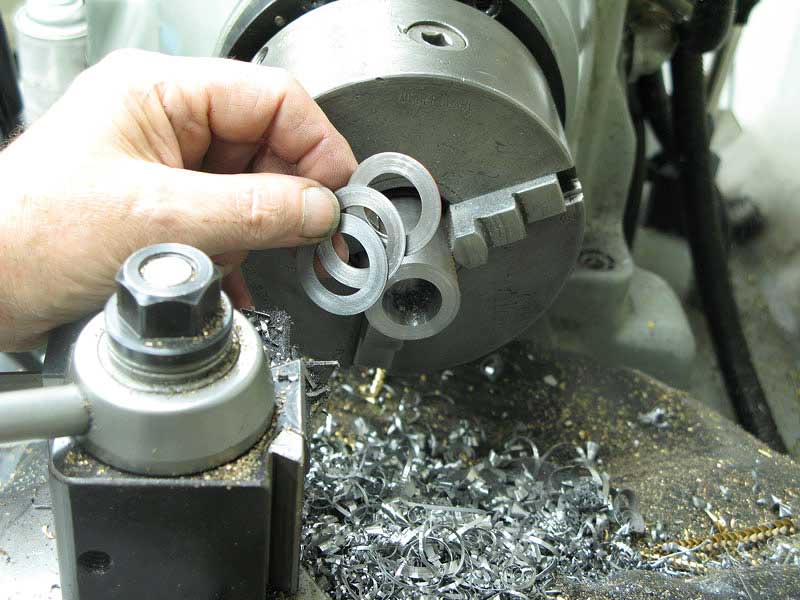
Time to make some bearings.
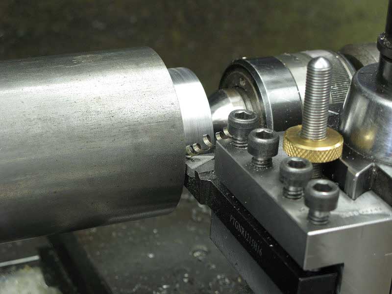
I made all three bearings in pretty much the same way, first turning the outside to be a slip fit (.003-.005" undersize) in the casting where I'd bored or reamed.
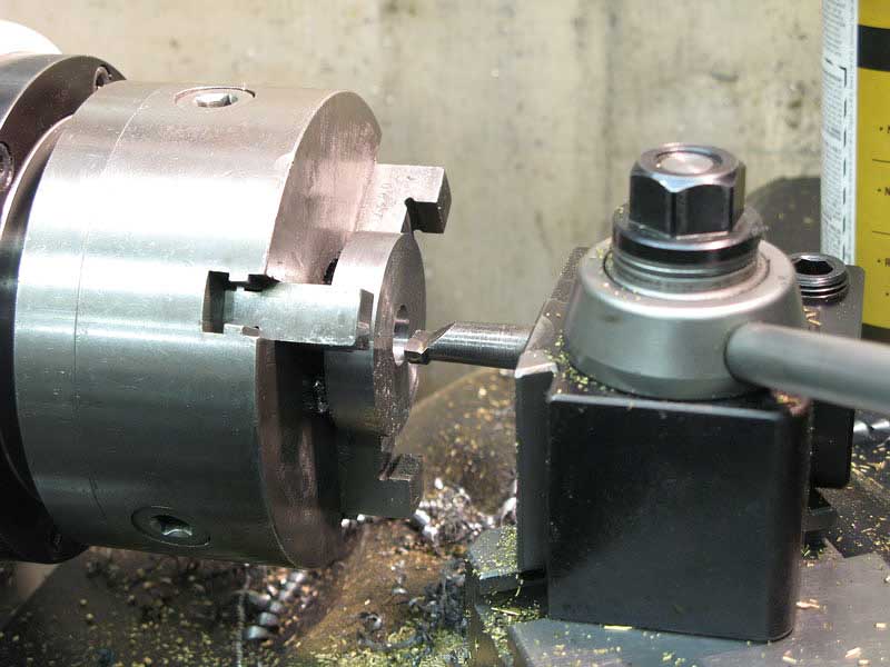
Bearing bronze is expensive stuff, so I was determined to waste as little as possible. First, I'd part off the length I'd use:
Then, center drill both ends:
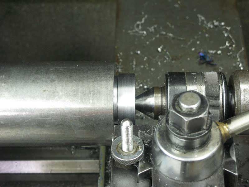
And, mount it between centers. Here I'm using my "drive center" so I can turn the entire piece without having a drive dog in the way:
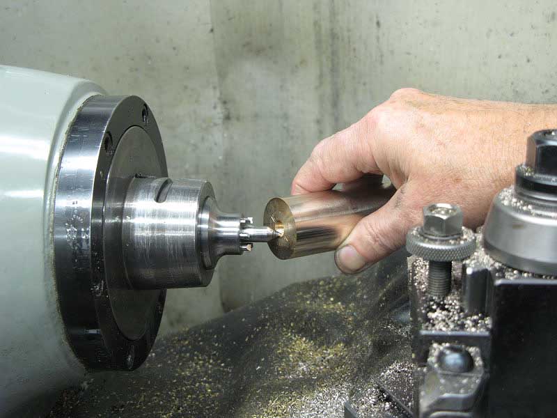
Because it's between centers, I could remove the piece for trial fitting in its future home:

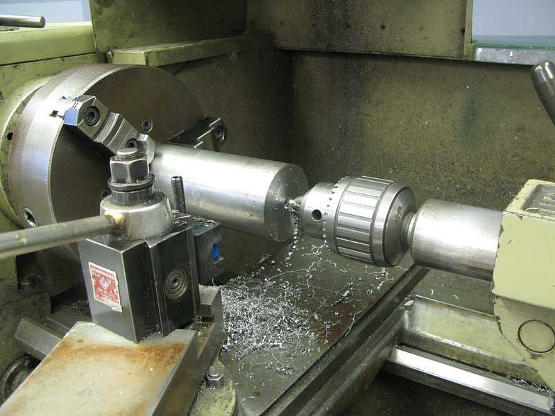
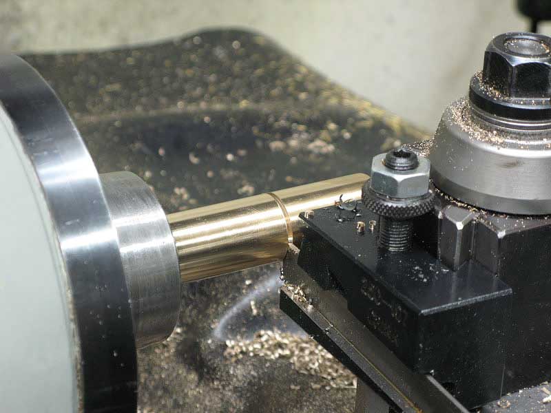
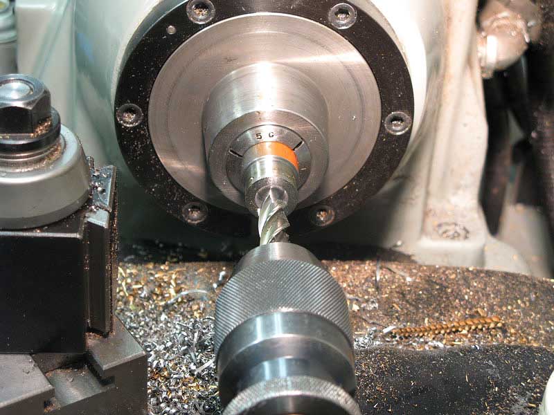
Once I had the O.D. established, I chucked and bored the hole for the 3/4" drive shaft or the 1/2" file rod:
A final touch with a 3/4" reamer gave me a nice fit for the drive shaft:
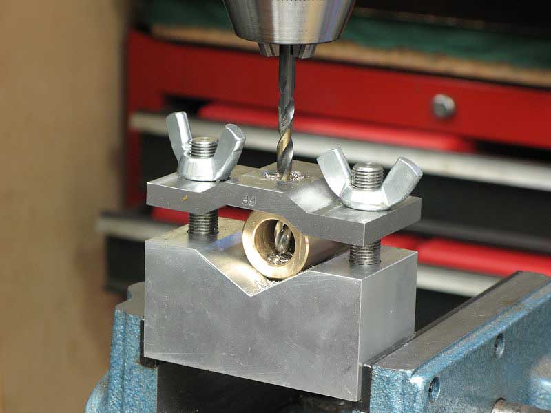
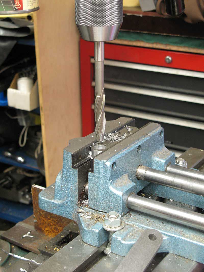
The inboard end of the drive shaft bearing sticks into the center of the casting, and it gets a 1/4" hole for oil to leak in to lubricate the bearing. I used my cross drilling jig on the drill press:
All three bearings went in the same way, slipped in with some green gap filling Loctite to secure them. I made the drive shaft bearing a bit over length so I could trial fit it to get just the right clearance with the file rod, yoke and crank in place:
Once I had it fitted right up, I marked the length with a knife so I could reinsert it to the proper depth:
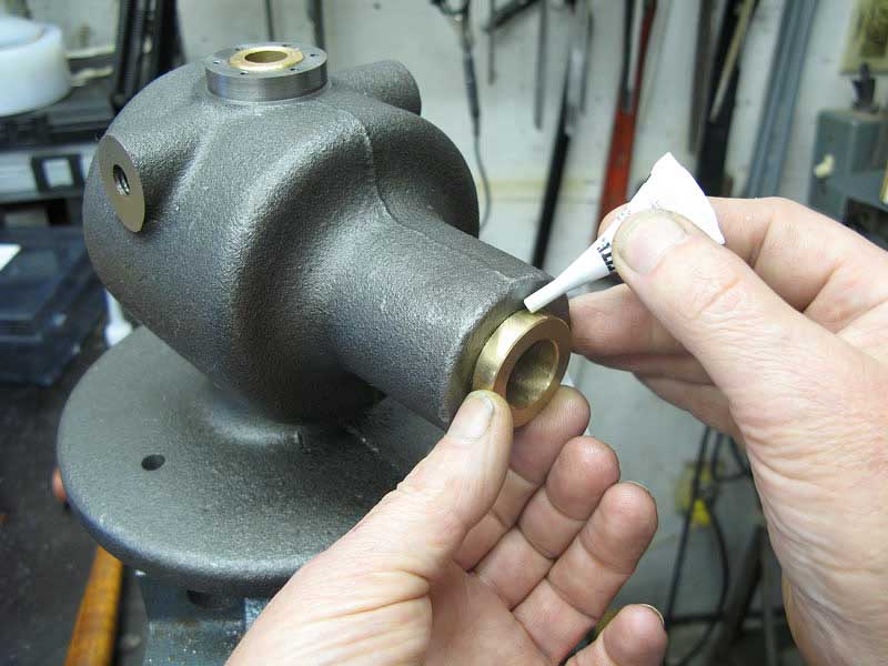
In it went, along with a generous coating of that green Loctite:
Glad I worked fast. As soon as I got the bearing in place the Loctite seized, and the job was done.
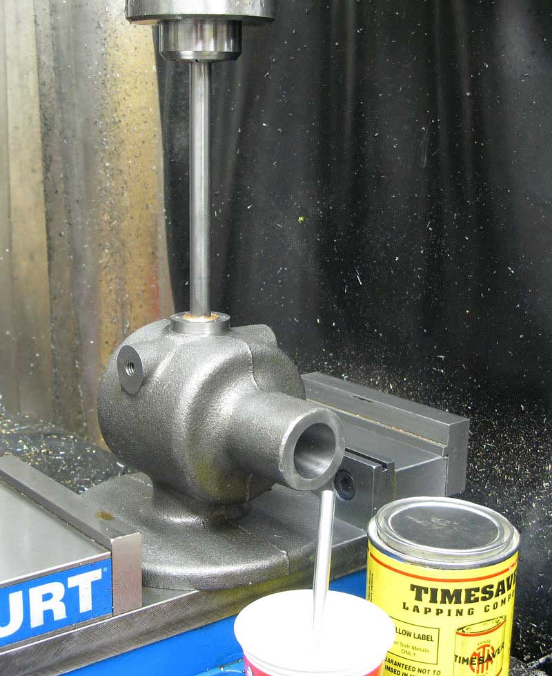
The file rod had just the very slightest tendency to bind in the upper and lower bearings, so I lapped them using a spare piece of the same drill rod I'd use to make the file rod:
It was just a minute's work with the yellow soft metal lapping compound.
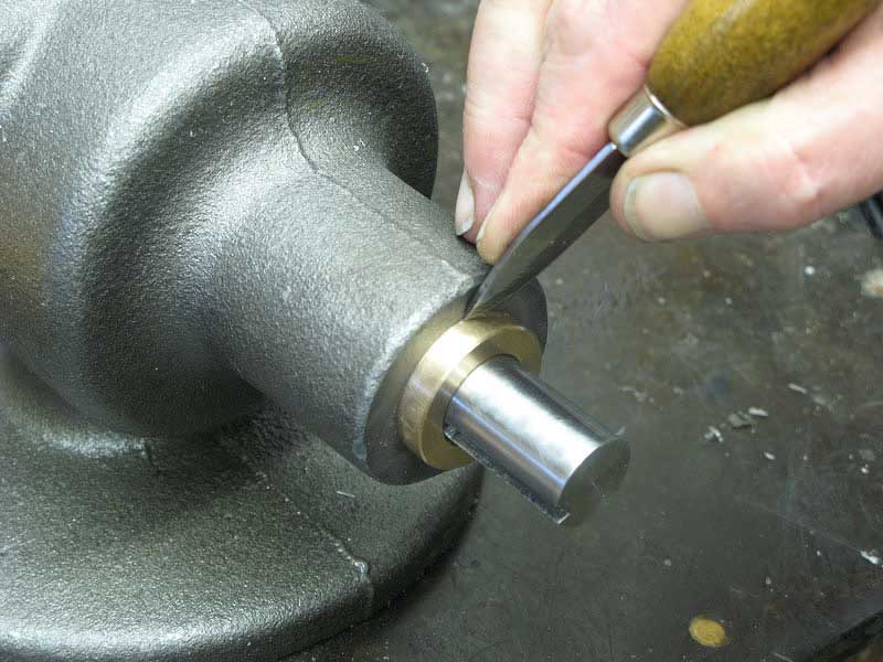
I milled off the protruding bit of the upper bearing flush with my milled surface on the casting:
And, I cleaned up the excess drive shaft bearing.
The file rod started out as a piece of 1/2" drill rod, and I drilled the bottom three inches deep to act as a sort of oil pump:
I drilled the upper end to receive the file tang, and cut away 1/2 of the diameter:
As the rod pumps up and down in the lower bearing, it naturally pumps a bit of oil, so a relief hole above the bearing would provide an escape for the trapped oil:
Andy suggested orienting the hole to squirt a bit toward the yoke, and that made sense to me.
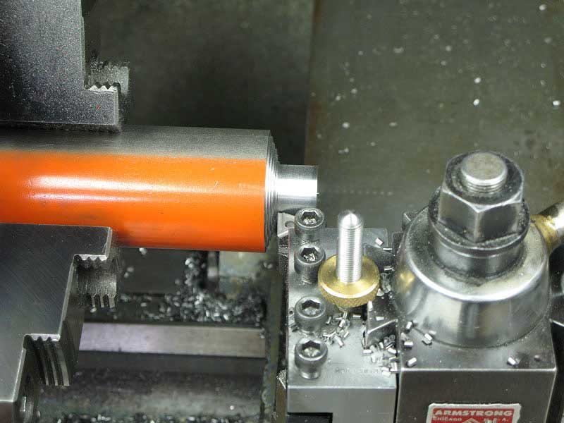
Wow, here we are back at TechShop. Once again, I took advantage of the large lathe to take a section off the end of a nice 2" diameter steel rod. (That orange paint is my personal shop code for 12L14 leaded free machining steel.)
While I was there, I turned the contour of the "hat" or clamp that holds the file on the end of the file rod. I slung the compound way around back to make quick work of that taper:
Parting off 2" steel is so much easier on a big lathe:
Back home, I stuck the hat backwards into a collet to finish the detail turning, first drilling:
And then boring to 1/2"
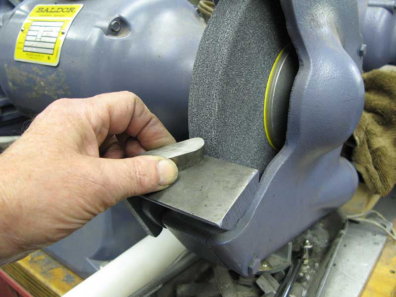
I ground a simple round nose HSS tool to turn the inside contour:
Form tools like this are easy to make, and often don't have to be particularly accurate to do a nice job:
Then on the mill, I drilled for a 10-32 set screw:
When tapping small holes on the mill, sometimes I do the job with the power off and simply turn the chuck by hand:
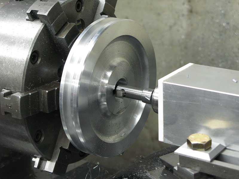
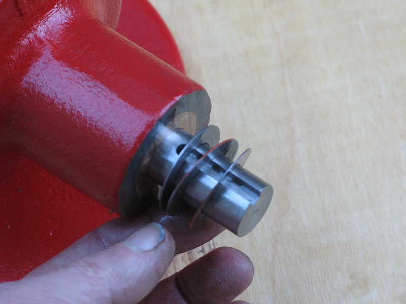
I got hold of a two-inch thick five-inch diameter aluminum disc to make my drive pulley. Chucked up in the four jaw, I was able to turn a shaft section down, and finish it with that same rounded form tool:
Reversing the piece and switching to a self-centering chuck, I finished off the pulley, first by trimming out the other side:
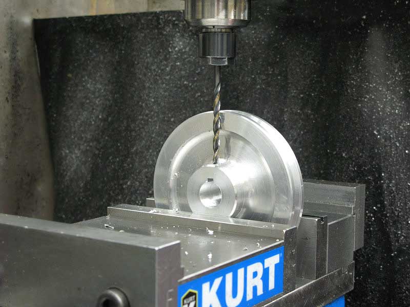
Then, drilling the center:
And, boring for a nice fit on my drive shaft:
I used a regular 1/8" parting blade to cut the V-belt groove to depth, and then set the compound to the right and left to achieve the required 38-degree included angle:
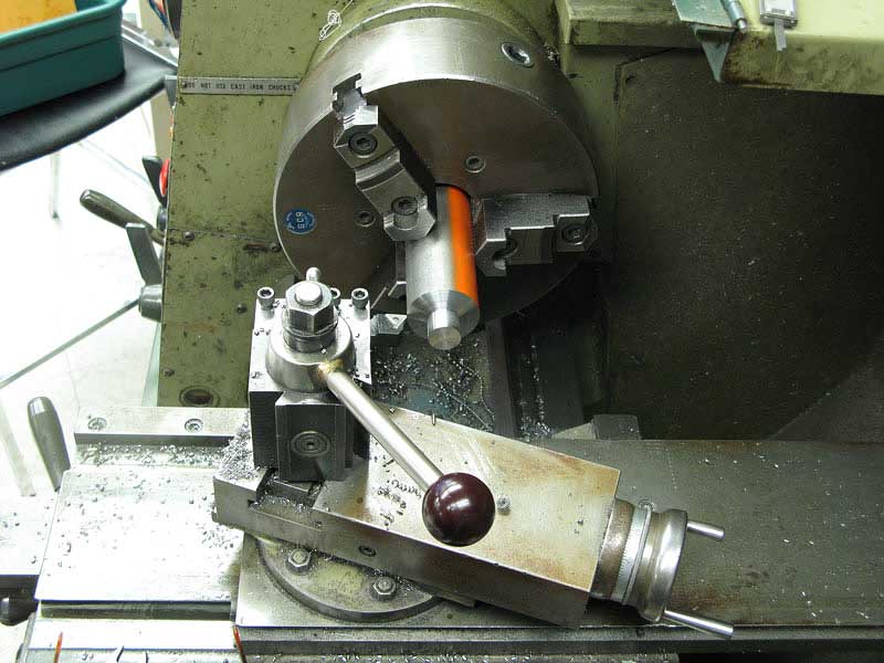
Ooh, here's the fun part. I get to use my lathe slotting tool.
I made up a nice little 3/16" cutter for the slotter, and, retracting the compound .001 each time, I took a lot of quick strokes and cut the keyway:
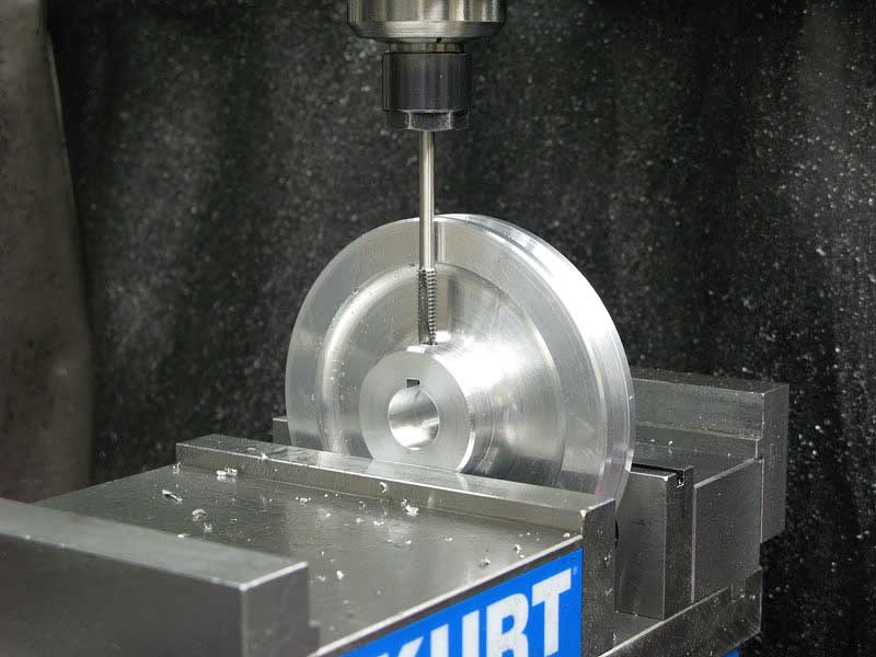
I used my Erickson collet holder to grip the drill bit and drilled the set screw hole:
Same setup to tap the hole under power for a set screw using a long 1/4-20 tap:
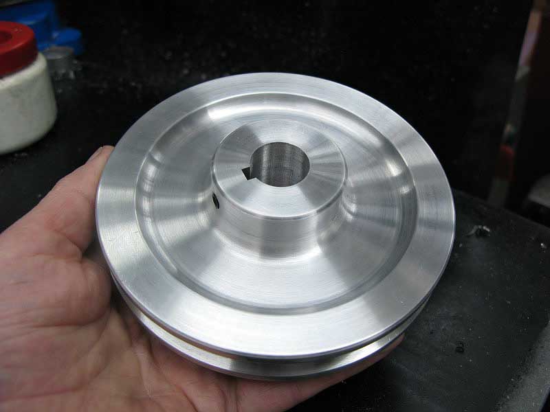
Here's the finished pulley:
The final casting is the table.
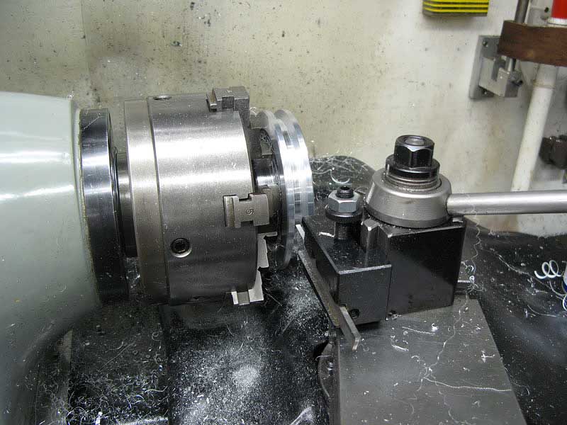
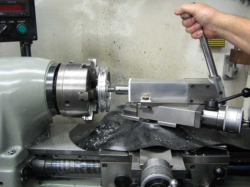
And this photo is the only one I "dummied" up. I took the table casting to TechShop and mounted it in the 15" Clausing lathe:
The lathe is big enough that I actually stand my tripod right in the chip pan to take photos. Unfortunately, it looks like I might have bumped it or forgotten to set the focus. As you can see, the table is painted at this point.
At any rate, I faced the table, and drilled it through center.
Back in my shop, I countersunk the hole from the back side:
Then, I milled the table support bosses flat:
While still having center registered on my DRO, I went to the outside of each boss and touched a 1/4" mill to scar the surface right on the centerline of the table and its hole:
Then I could setup my angle block on the vise, and drill each of the mounting holes directly on center and at the same height from the surface of the table:
The boss is just far enough down from the edge of the table that I had to use a tap extender to reach it:
The table support brackets are simple pieces of 1" X 1/2" cold rolled steel. I drilled each end for 3/8" cap screws.
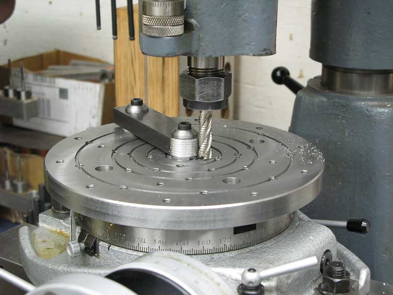
I keep a small rotary table mounted on my small Rusnok mill most of the time, just for little jobs like this one. Some time ago, I'd made up an eight-inch diameter tooling plate and set it up on the six-inch table. I milled the center hole in place, so I know it's accurate, and I threaded the bottom to accept simple tooling. In this case, it's a plug that's 3/8" diameter on top to fit my table support brackets:
The bracket plugs right onto the center:
And, I was able to bolt the support bracket at both ends to hold it securely. A quick trip around with a roughing end mill and I had the ends rounded off neatly:
Over at the drill press, I countersunk the support brackets for their mounting screws:
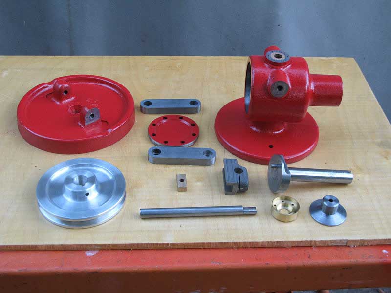
Here's a quick shot of the major pieces, ready for assembly:
In went the crankshaft:
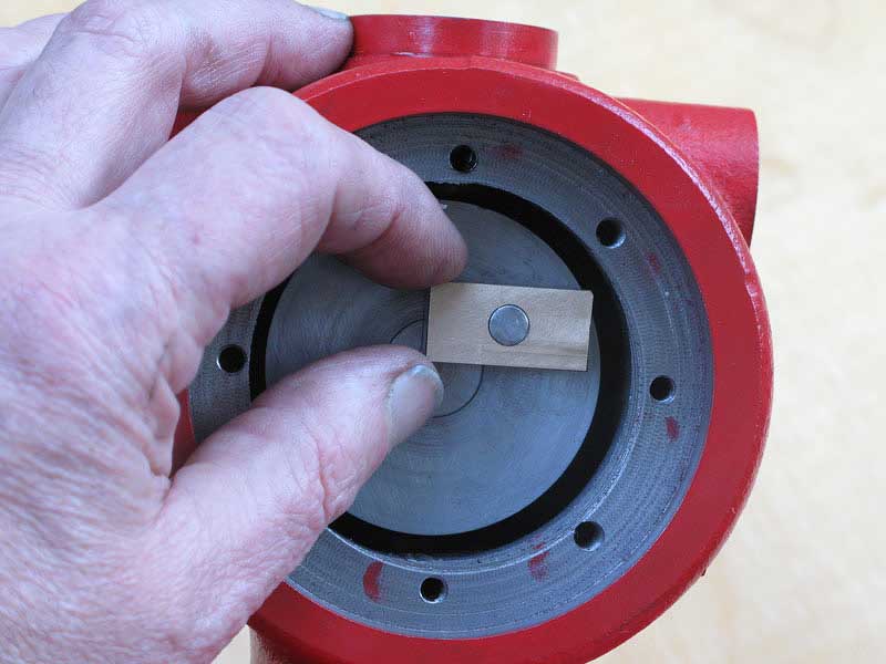
And the bronze slider:
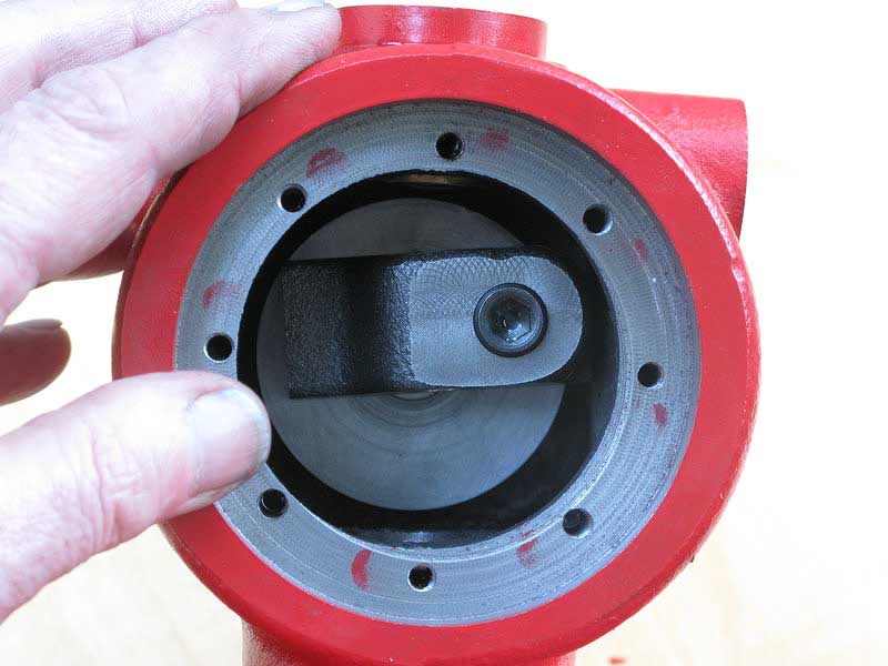
The yoke:
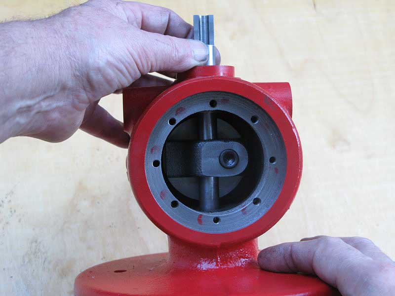
And the file rod:
There was just an eeny bit more lateral movement in the drive shaft than I thought I'd like, so I went over to the lathe and turned out a series of thin spacer washers, from about .005" to .020".
After finding just the right one to get the rig running tight and smooth, I stashed the spares on the other end of the drive shaft, behind the pulley. That way, if I ever needed one to compensate for wear, I couldn't avoid being able to find it:
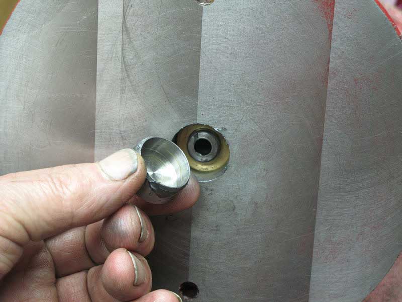
The bottom of the casting needed a plug to keep all that nice oil in there, so I made one from a piece of steel:
I swabbed the surface with some super high pressure nickel grease because I'd made a tight press fit:
Here's the cap"
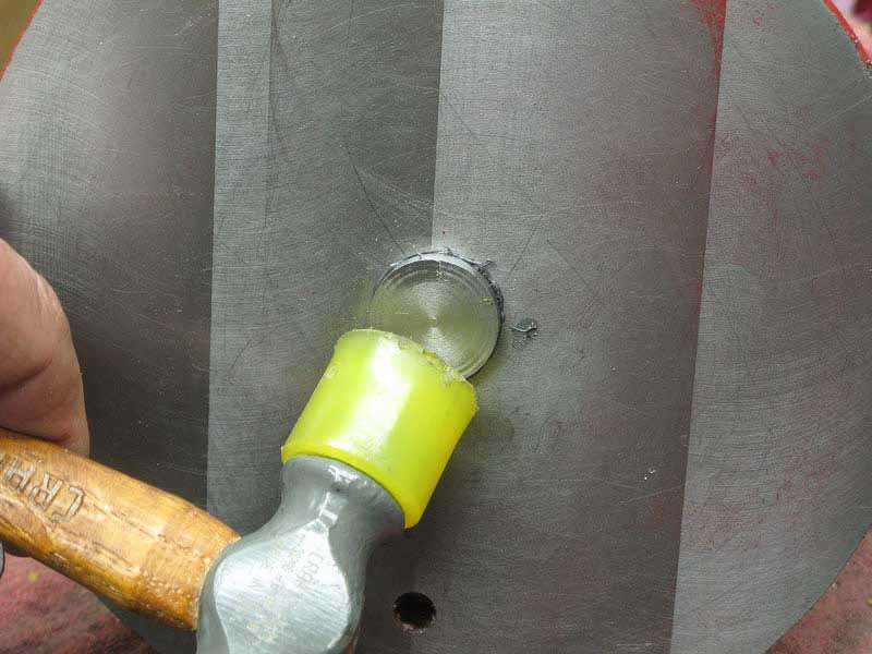
A couple of swats with a plastic hammer got it started:
But I had to clunk it hard to slam it in flush:
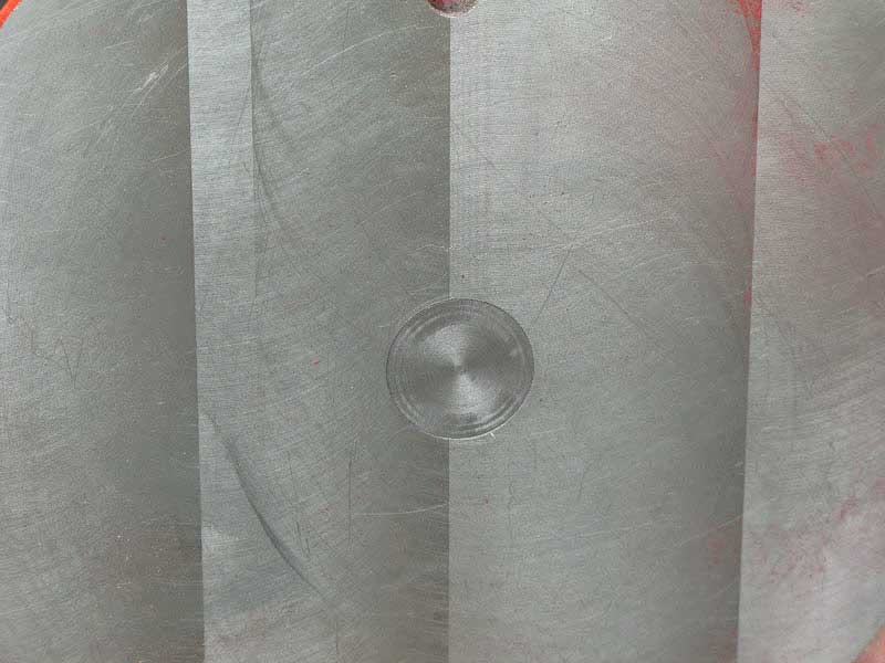
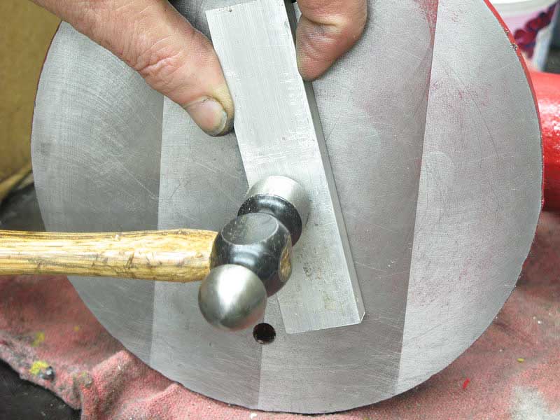
That aluminum plate kept me from scarring the bottom of the casting:
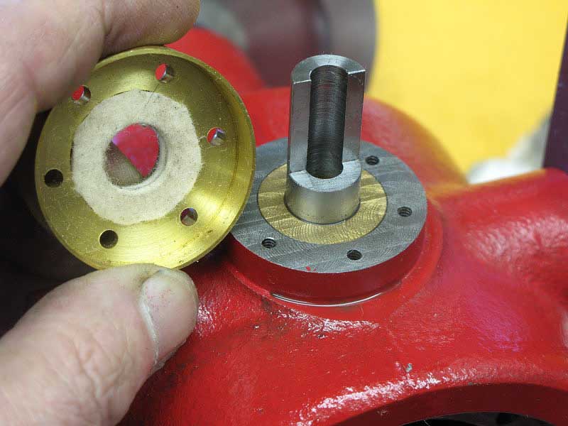
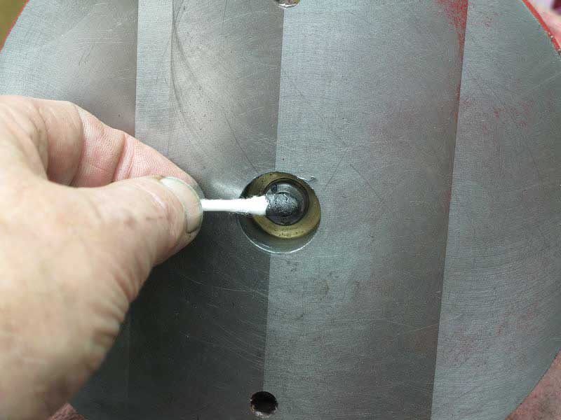
The upper cap got a little felt washer to keep out chips and dirt:
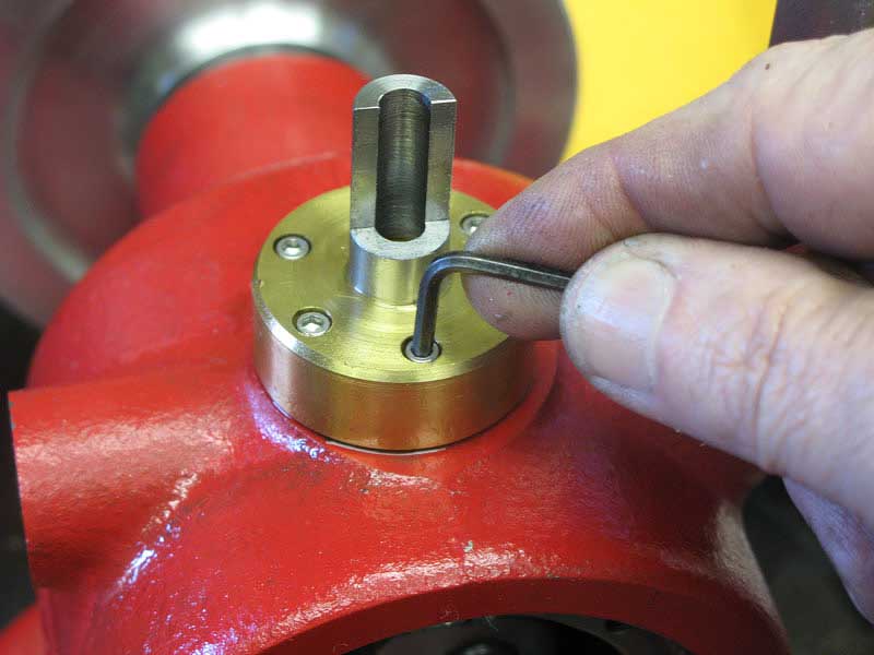
I screwed it down tightly with the six 4-40 cap screws:
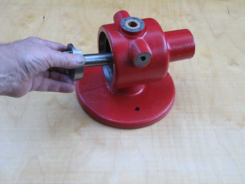
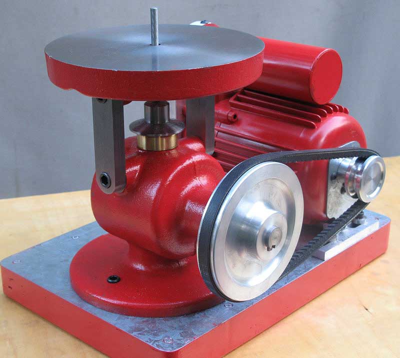
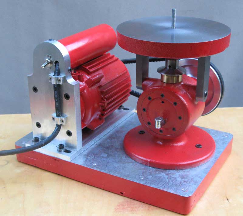
And here's the little bugger, ready for action:
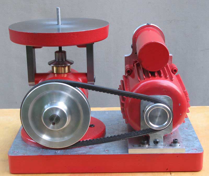
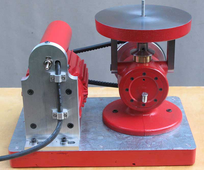
I looked all around for a small motor to drive the thing, and finally settled on dismembering a cheap pressure washer I'd bought from Harbor Freight. The stupid thing started acting up after only a couple of uses, and it became obvious I'd never use it again. I salvaged the motor, and, after only a couple dozen hours of fiddling, I was able to mount the thing, paint it red, and get this project finished:
Update, 10/30/07:
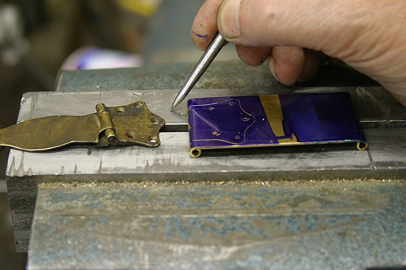
I finally put the filer to work.
My first little project was to make a new pair of latches for a vintage 1867 Martin guitar case:
I just broke off a 1/4" diameter chainsaw file and stuck it in the holder, with the teeth pointing downward. It made quick work of cleaning up the curvy contour, working right up to my scribed line:
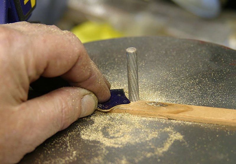
I was pleasantly surprised at how easy it is to hold the part down by hand.
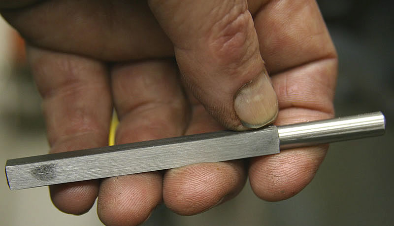
Not having a square file with a 1/4" shank, I thought I'd try my hand at actually making one, so I turned down the end of a 1/4" square piece of W-1 tool steel:
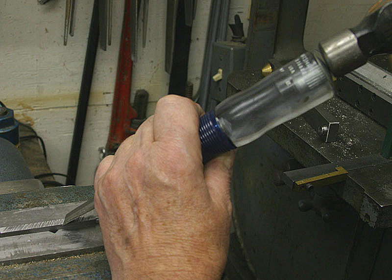
Using a plain old cheap wood chisel, I whacked a bunch of teeth in my file blank:
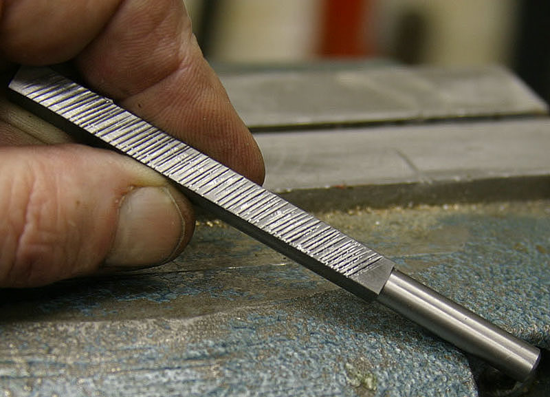
Not too neat to look at, but these teeth are pretty sharp:
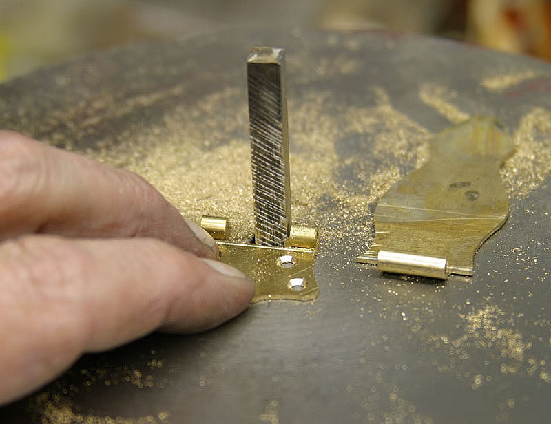
After heating to bright cherry red and plunging it in water, I mounted my file, and found that it didn't work as well as the chainsaw file, but it cut quickly and easily enough:
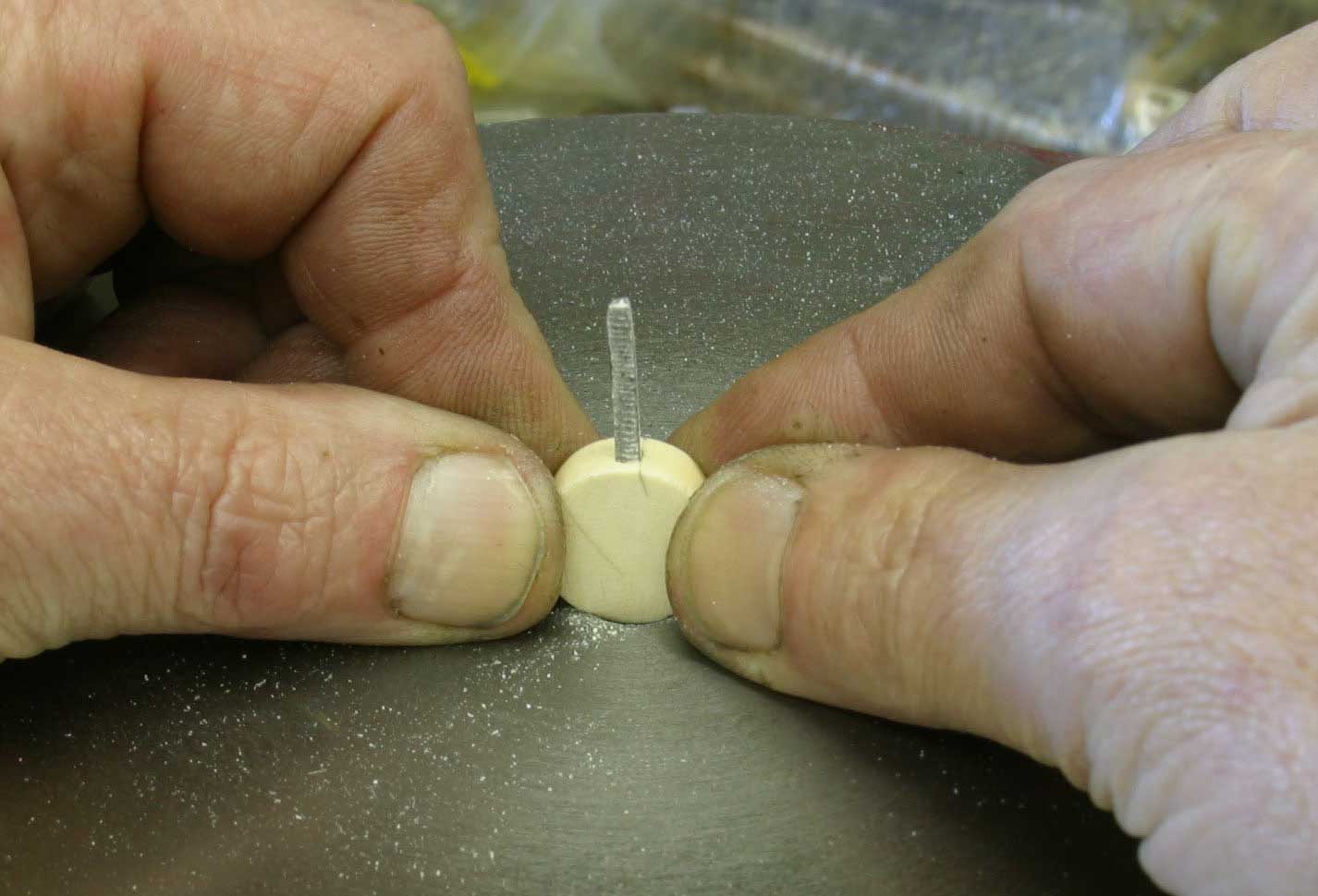
Here's another little job. It's a replacement ivory button for the tuning machine of the guitar that fits in that 1867 case:
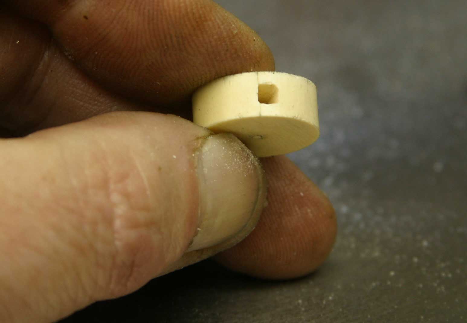
As before, I made the little file to fit the job, and it took less time to make the file AND square up this hole than it would have for me to have filed the hole by hand: