
The "Two Slider"
Make this classic mechanism
Here's a basic milling project that should give you some interesting operations to perform, including a fair workout on the digital readout (DRO) commonly found on many milling machines. You'll get into milling and squaring stock, slotting, drilling, hand tapping, edge finding, centering and other standard milling techniques.
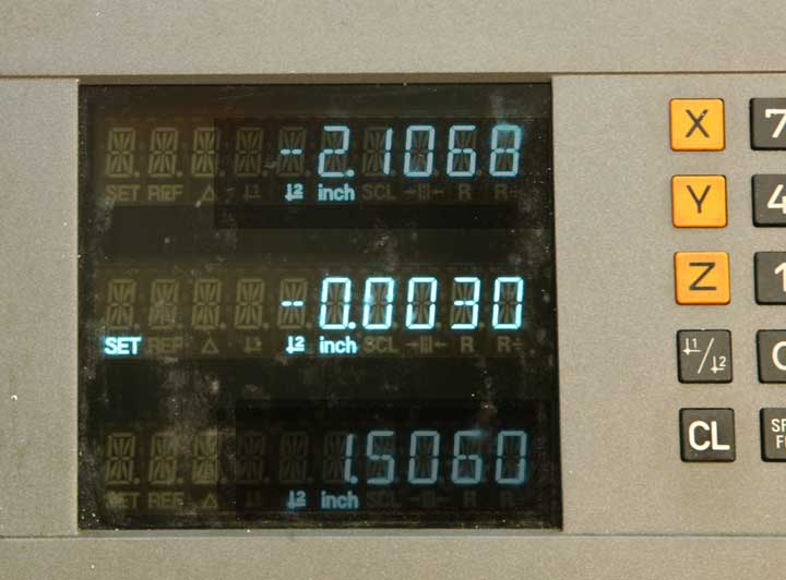
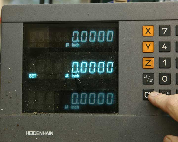
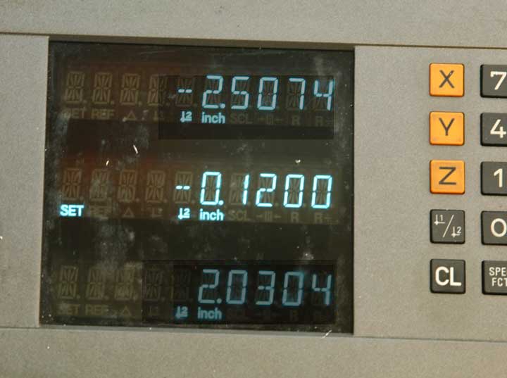
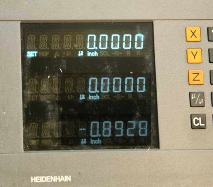
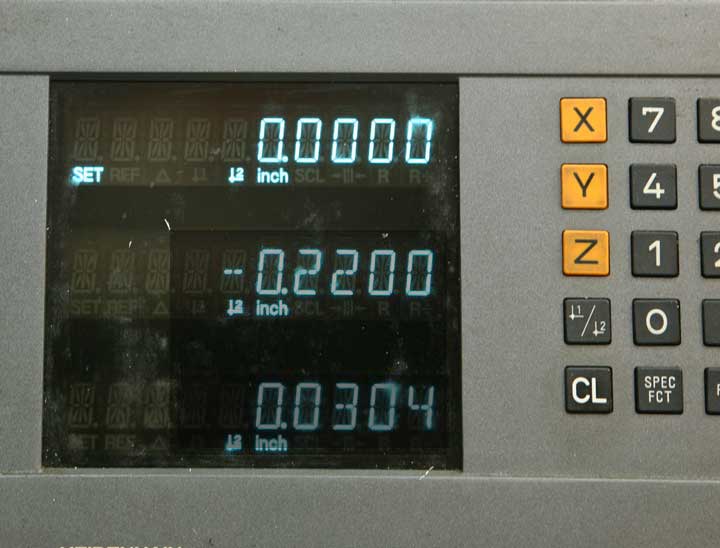
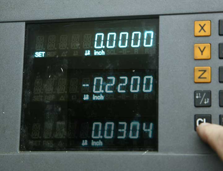
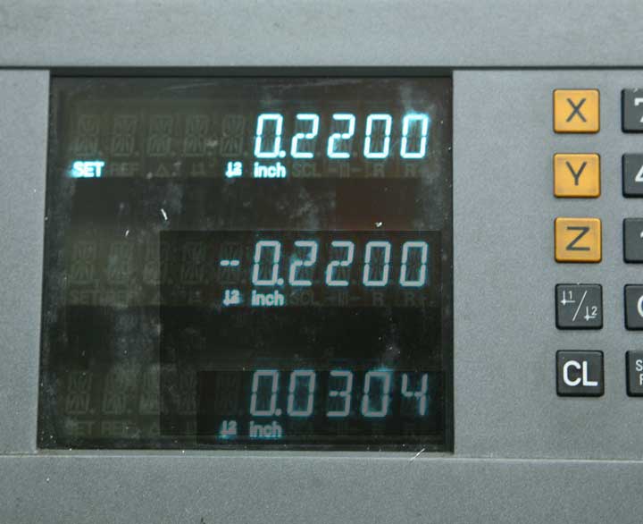
DRO units vary a bit, so to make things a little more clear, I've dimmed the display on the axes that are not in use for each particular measurement. While this milling machine has a Z-axis scale, I've dimmed it a bit more because I'm not using it for this tutorial because the mill you're likely to encounter may have only X and Y scales.
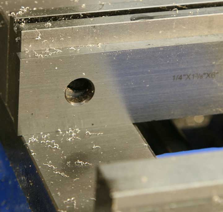
The metal stock for this project includes a piece of aluminum for the base, 5/8" thick and roughly 4" square, a small rectangular piece of brass for the slider, a small piece of aluminum for the handle, and a short section of 3/8" diameter brass rod for the swivel handle.
Three screws complete the hardware kit - 2 each, 10-32 button head screws, and one 10-32 socket head cap screw.
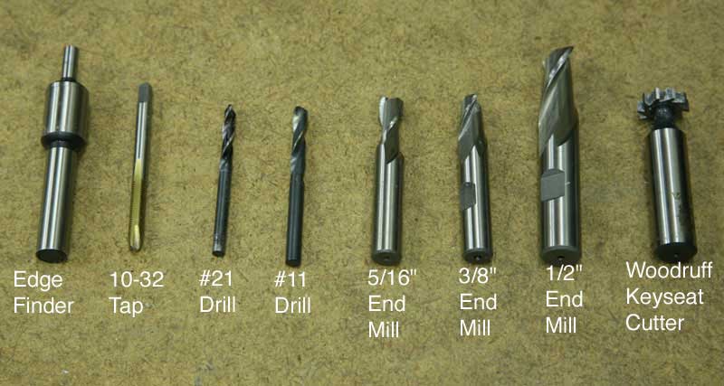
Here are the basic cutting and collet mounted tools you'll be using. The edge finder, which fits either in a collet or drill chuck, is on the far left. Then proceeding to the right, the 10-32 tap, #21 drill, #11 drill, 5/16" end mill, 3/8" end mill, 1/2" end mill, and the T-slot or Woodruff key seat cutter. The drills are of the "split point" style, which allows them to start and drill right on center, eliminating the need for spotting drills to guide the drilling.
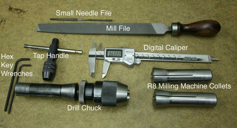
Other tools include a mill file, needle file, tap handle, drill chuck, various milling machine collets, hex wrenches and a digital caliper.
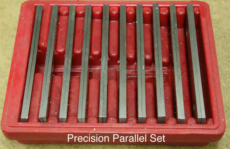
For holding work parallel in the vise, there's a set of precision ground parallels.
OK, before getting started, now's the time to check to see that the milling machine is setup and ready to use. If you're not familiar with this basic routine, jump over to this little description:
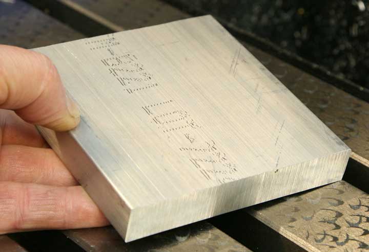
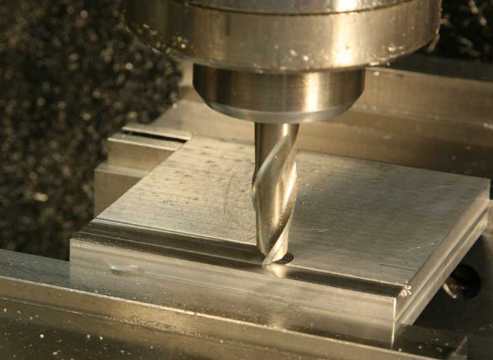
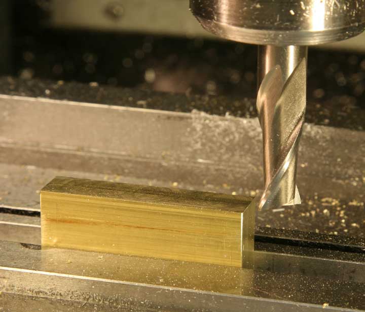
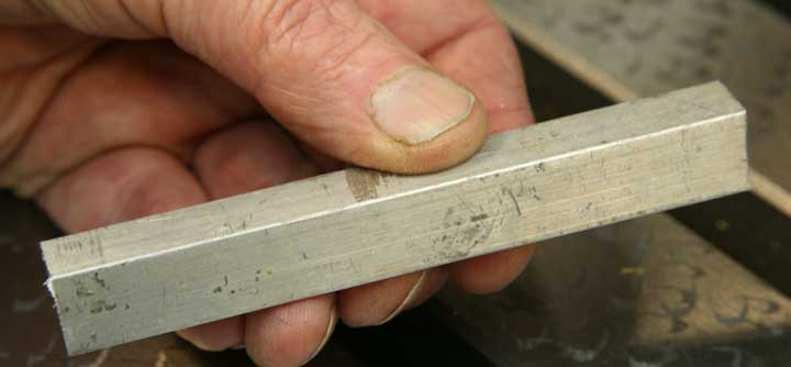
The base is the most complex part of this assembly, and it's the logical first piece to make because other parts have to fit it with a fair degree of precision. This is a 4" x 4" piece of 5/8" thick extruded aluminum. While some surfaces appear flat they are not as flat or square as the might be. Two edges are quite rough because the piece was sawed off a longer section.
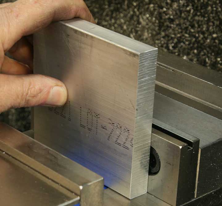
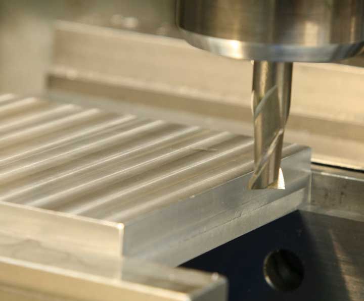
The first step in truing up the stock is to place one of the straightest edges downward in the mill vise so the top edge can be milled flat. There's a lot of material sticking up from the vise jaws, so you have a serious limitation on the force you can apply without causing excess vibration. You'll be taking light cuts so this 5/8" thick aluminum can stand up to the cutting action.
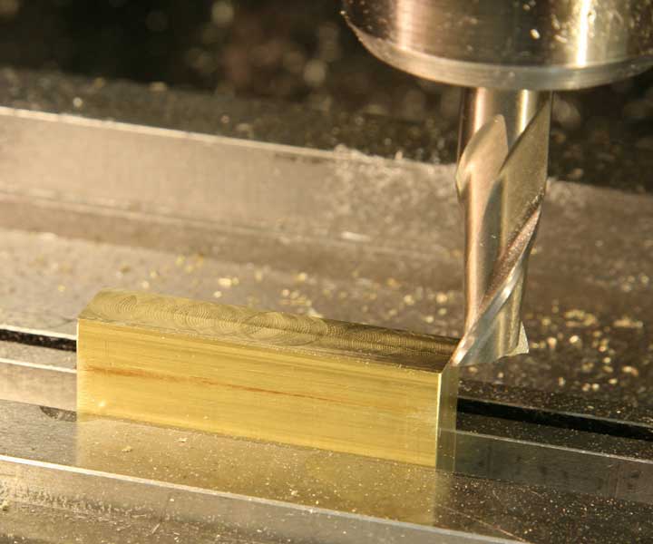
With the 1/2" end mill held in a collet, take a light cuts across the top of the stock in two passes. If you run the mill from right to left in the front, and from left to right at the back edge, you'll be "climb cutting," which will create less of a ragged bur on the corners of the work piece. Remember, your goal is to produce a smooth, flat surface without taking off any more stock than necessary.
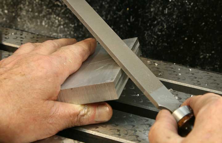
After each milling operation, be sure to clean up any rough edges or corners by filing lightly. Not only will that make the piece safer to handle with your fingers, it will assure that the metal can be clamped in the vise without having the rough edge interfere with alignment. Even though the vise is obviously very strong, it is still important to keep any little pieces of aluminum from being trapped when the work piece is clamped.
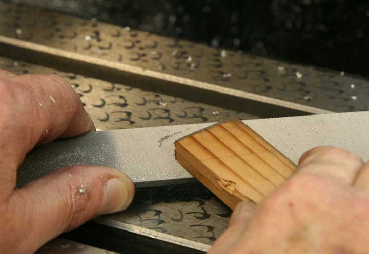
Clean the file frequently. The easiest and best file cleaner is a simple piece of hardwood you can simply push along the teeth of the file to clean them. A clogged file will not only scratch your work, it will simply not cut well at all.
Now, clamp the aluminum block in the vise making sure to seat the freshly cut edge down against the bottom of the vise to get a good alignment. Make a similar cut across the top edge to clean and straighten it just as before.
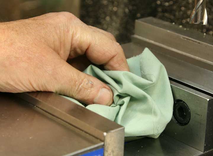
Here's a reminder. Always brush chips away from the vise, and use a rag to clean the clamping area completely. The same goes for the work piece. You can't get it square and true without working cleanly.
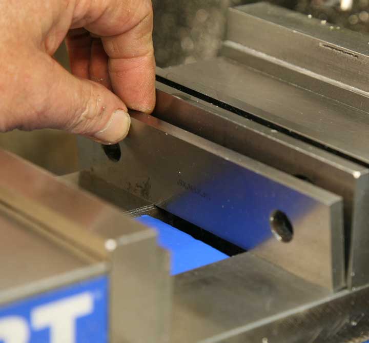
Wipe off and place a pair of parallels in the vise jaws to support the work piece. Select a pair that will allow plenty of gripping area for the aluminum - at least half of its thickness.
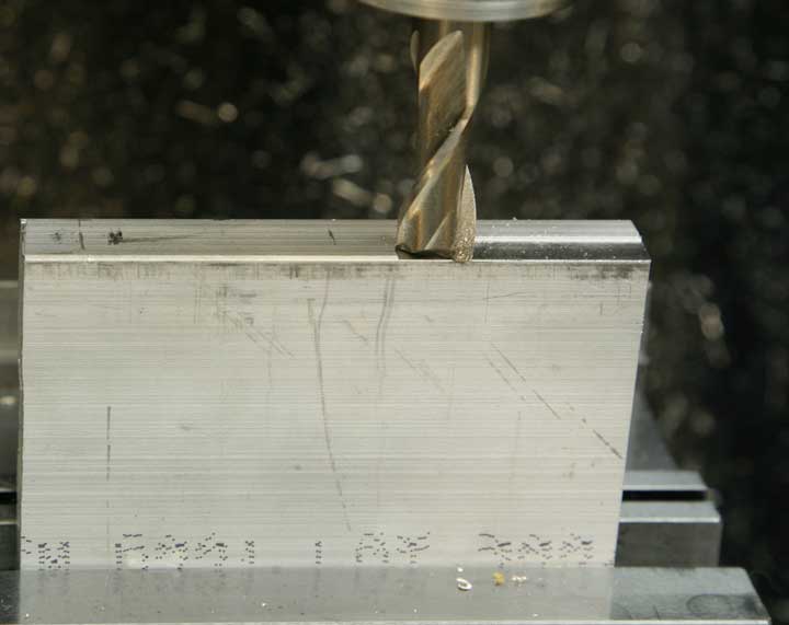
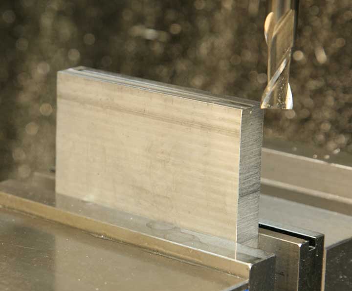
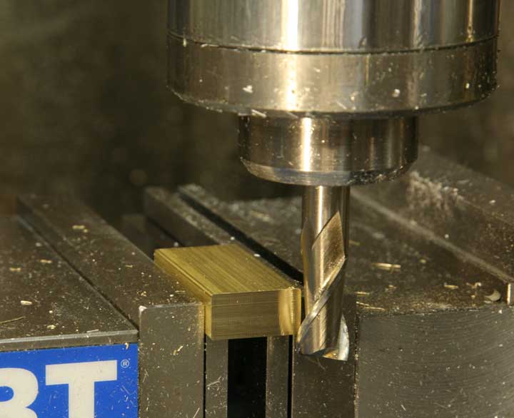
One really good reason for squaring stock is so that it can be held rigidly in the milling vise. Clamp the work piece in the vise using the newly milled surfaces to contact each vise jaw, and have about 1/2" of the stock hanging outboard so the edge can be milled with the side of the 1/2" end mill. Take a light cut or two, just until you have a nice flat cut across the end. Once again, climb cutting will provide a smoother surface. After you make that cut, turn the piece around and cut the other edge.
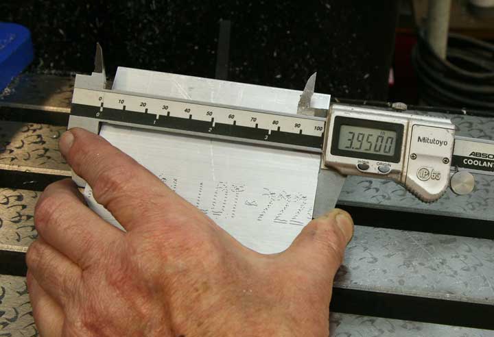
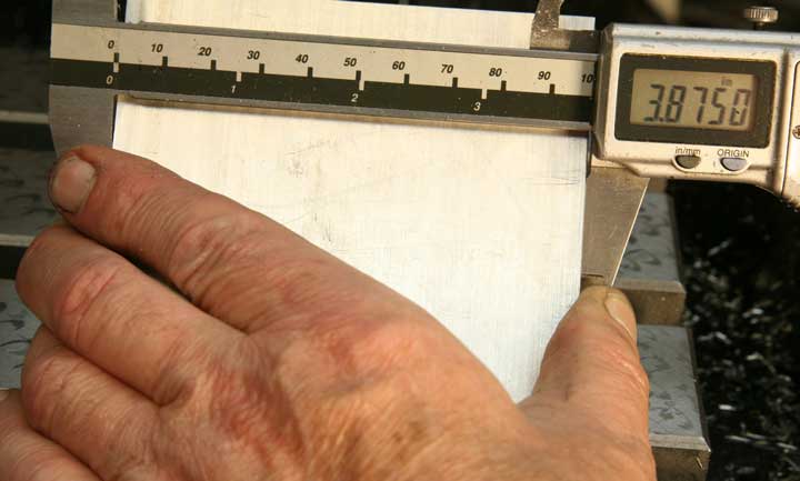
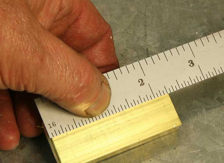
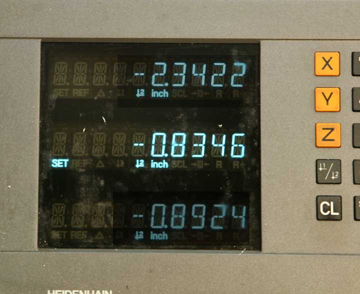
Now you have a nice block with edges that are parallel and at right angles to each other. It's time to square up the piece so all sides are the same length. Measure the shortest dimension across the block. It should be just a bit less than the original 4" dimension.
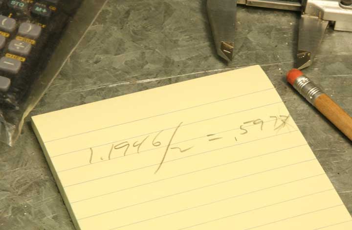
You'll want to have a finished piece that's 3.875" by 3.875" and you can achieve that with a simple bit of calculation and use of the Z-axis dial. First, subtract 3.875 from the current dimension to derive the amount you'll need to cut off.
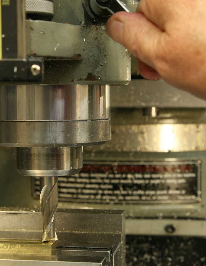
Clamp the aluminum in the mill vise so that the dimension you just measured is oriented vertically. Use the quill to lower the 1/2" end mill until it just touches the top edge of the piece. Lock the quill, and crank the X-axis handle until the end mill is no longer directly above the piece.
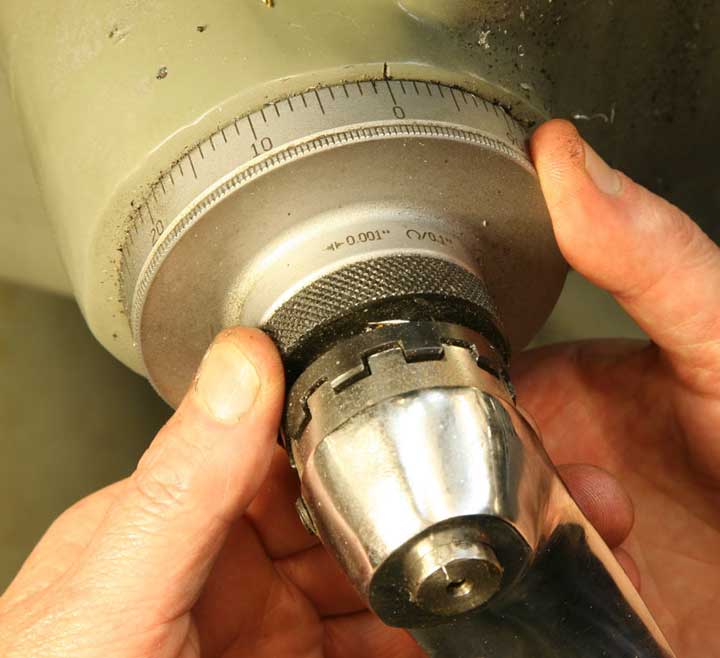
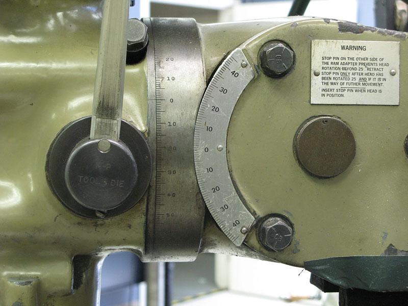
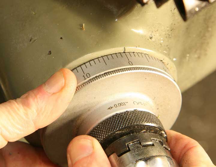
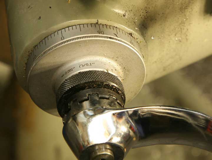
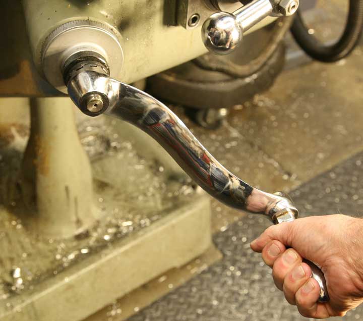
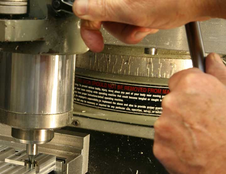
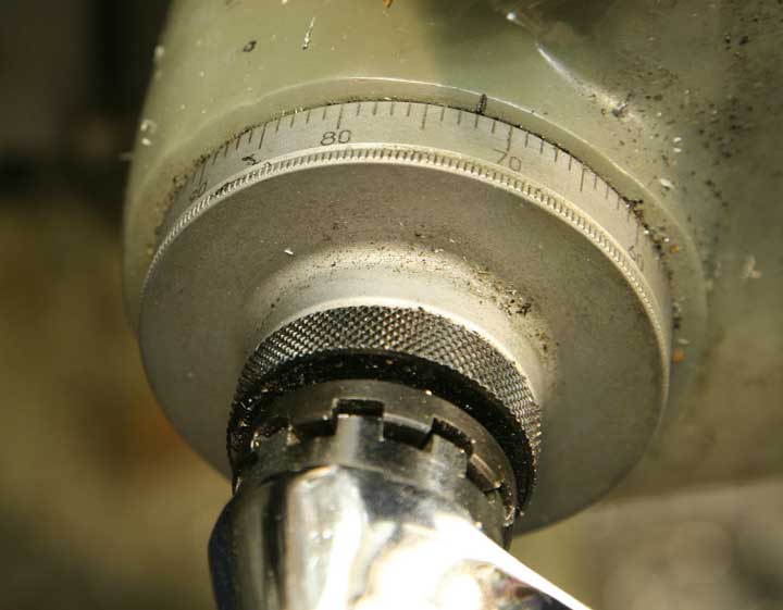
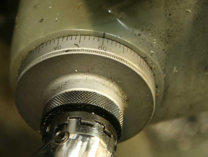
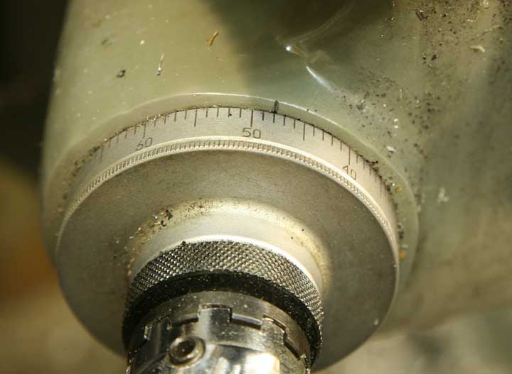
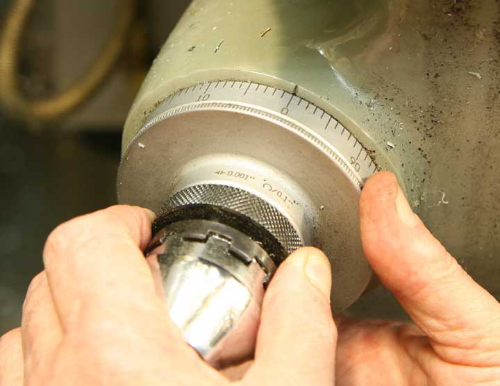
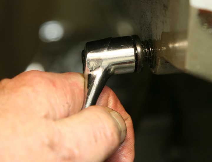
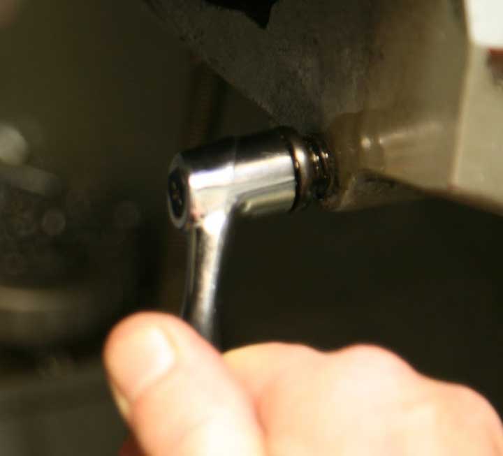
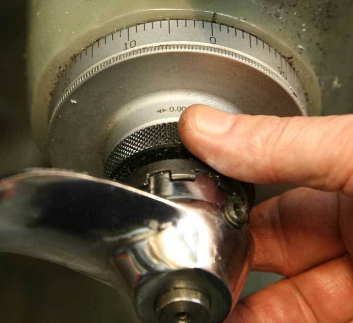
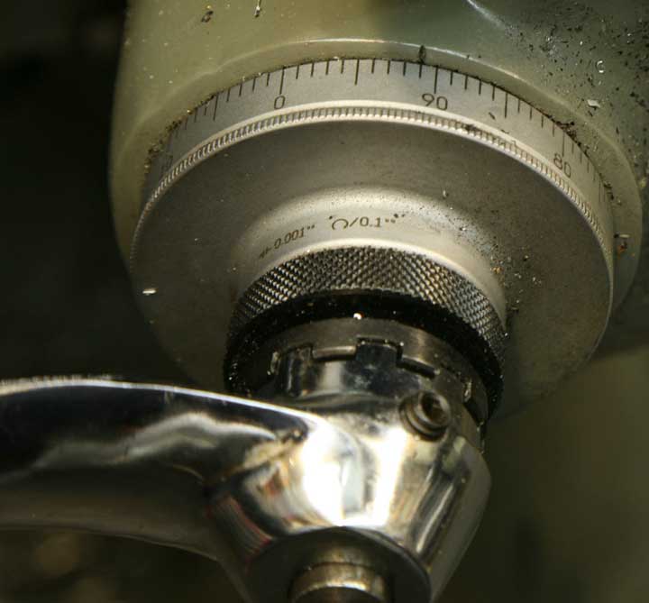
This is the dial on the "knee" or "Z-axis" of the milling machine. Loosen the locking collar, rotate the dial until it reads "zero" and lock the collar.
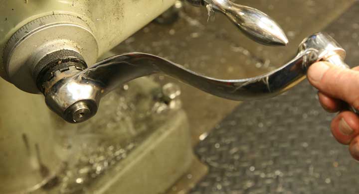
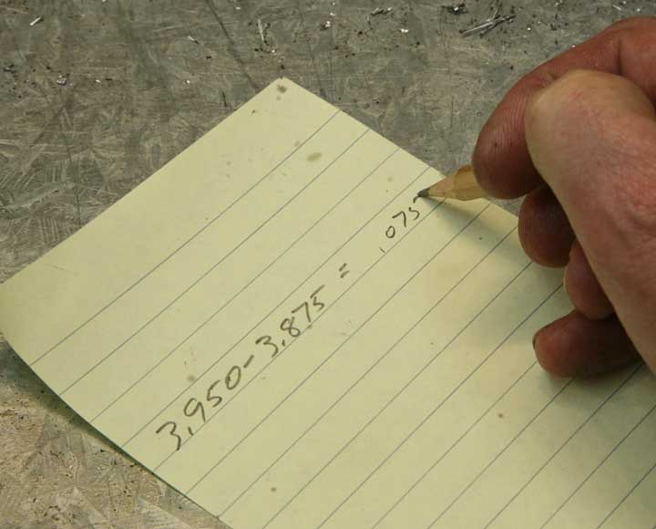
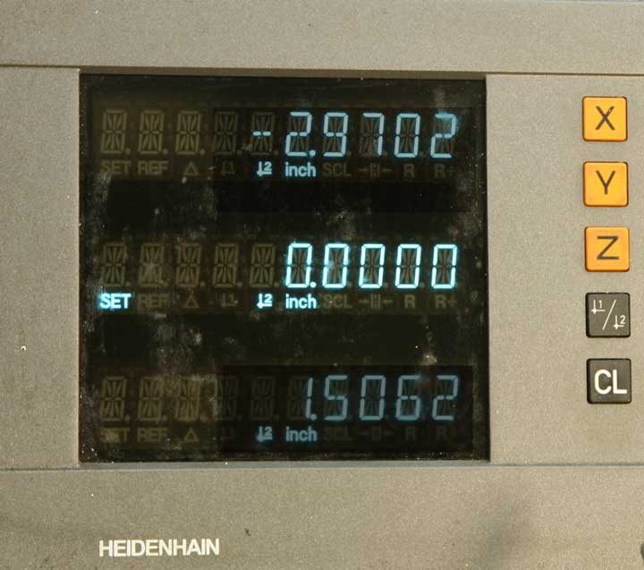
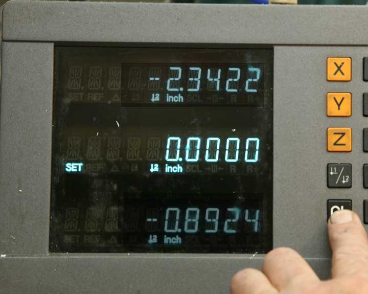
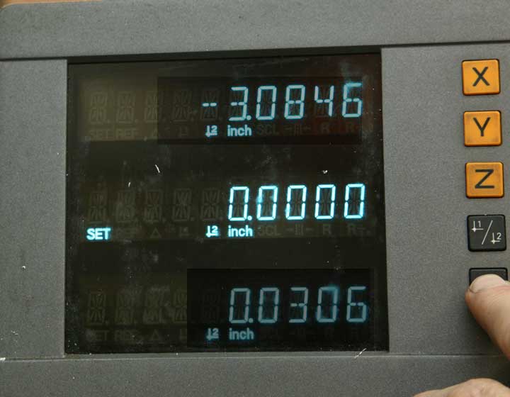
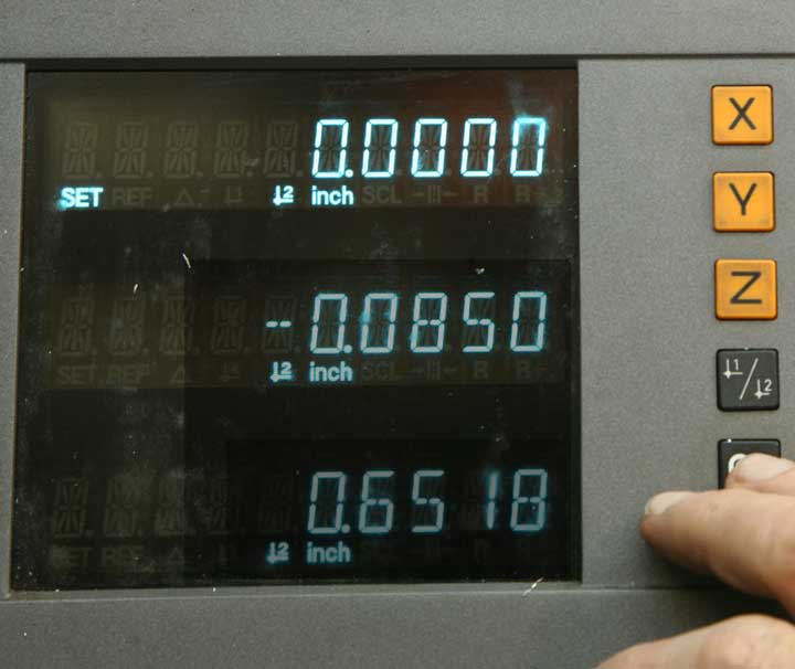
Now, raise the knee axis by the amount you calculated. As you can see, my calculation was .075, and my Z-axis reading is the same. This particular milling machine has a digital readout on the Z-axis, but that's rather uncommon. Most mills that are fitted with DRO units only on the X-axis and Y-axis. So, while you'll be using the DRO for other measurements, it's best to count on the graduated dial for this Z-axis movement.
With the table raised the appropriate amount, take a cut across the top of the piece just as before, in two passes, climb cutting to the left on the front and to the right on the back. File any rough edges, and clamp the piece, rotating it ninety degrees to cut the other dimension with the same table height.
If you were careful in measurement, clamping and adjustments, you should have a nice square work piece, 3.875 x 3.875.
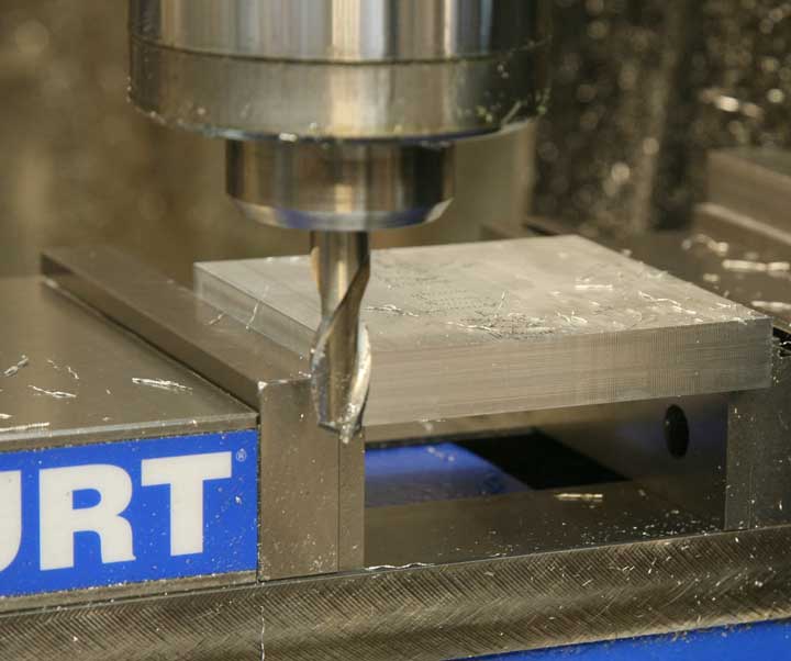
Clamp the work piece back in the vise supported by parallels, and take a light cut across the top.
If you go very lightly, you'll see how uneven the original surface was. Notice that the piece is actually a bit thinner in the center than at the edges. Raise the knee a tiny bit, and continue cutting until the surface is nicely flat and smooth. Flip the piece over, and repeat the process on the other side.
You now have a nice square piece that's flat on all edges. There's no critical dimension for thickness, so once it's smooth and flat, it's ready to go.
Once again, another reminder. Keep the clamping area clean of chips. Little flakes of aluminum like these may seem innocuous, but they will get squished against the vise jaws and mar the nice surface you just milled. Keep it clean.
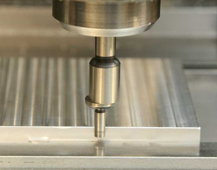
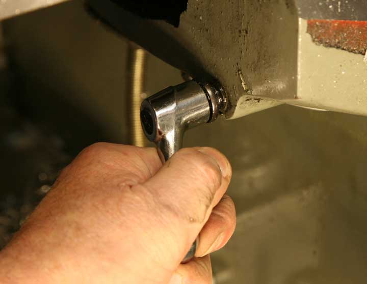
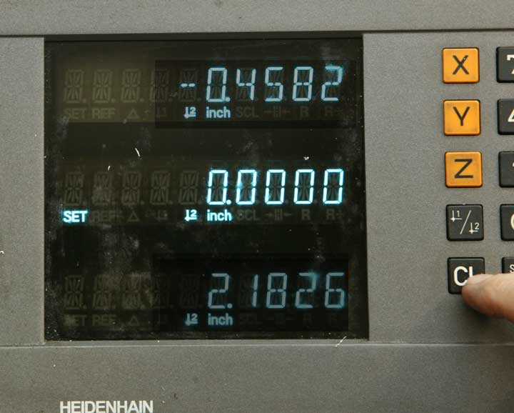
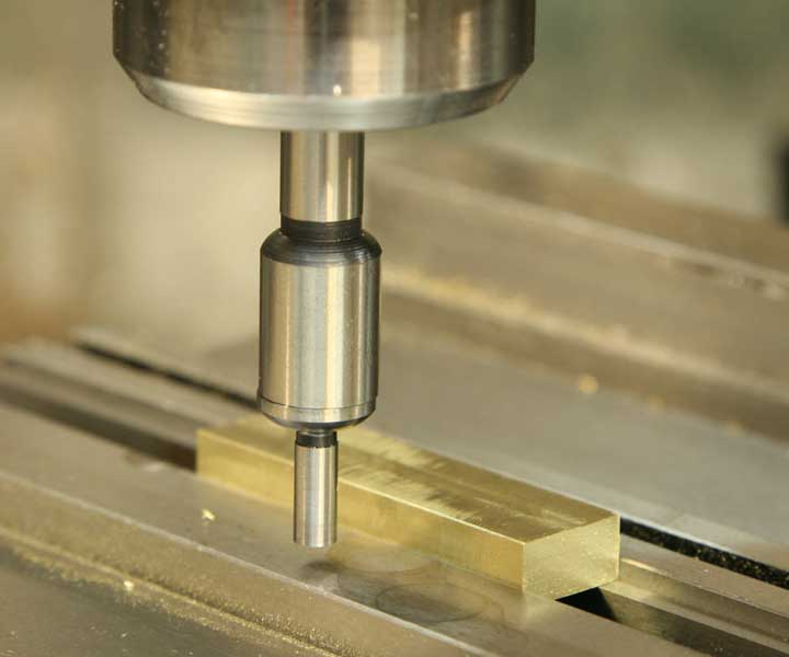
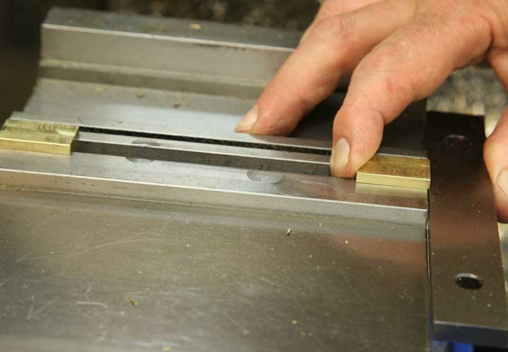
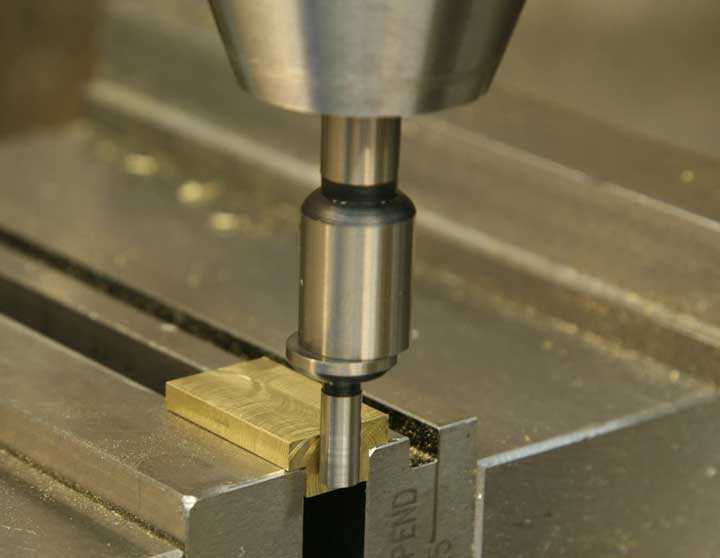
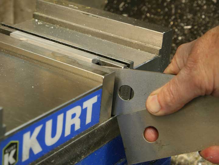
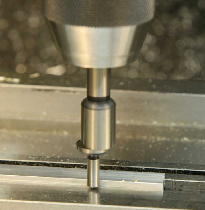
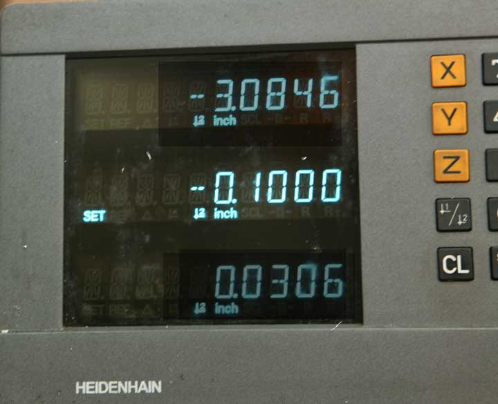
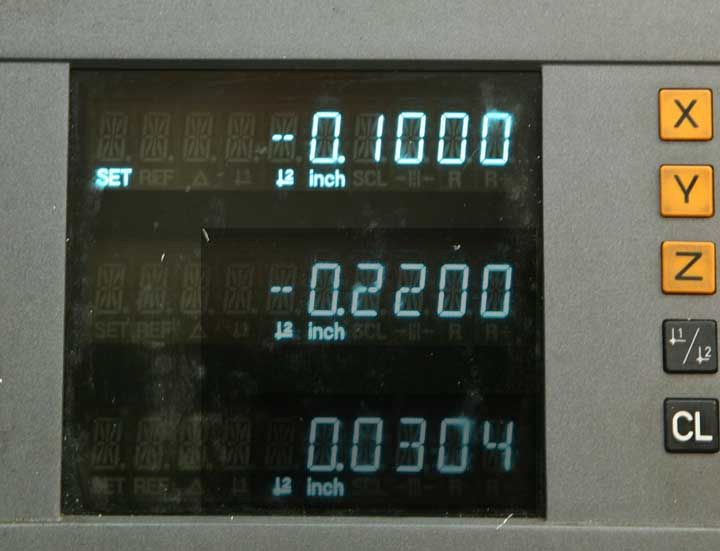
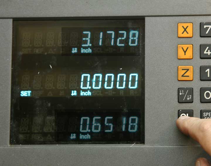
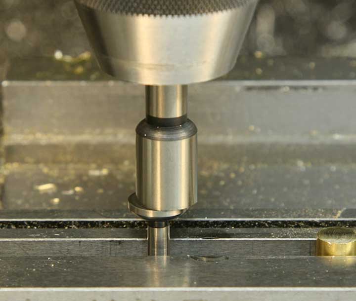
OK, now it's time to get serious about measuring. While the DRO can help you position the milling cutter precisely, you have to start from a known reference - the edge. This edge finder is just about the most important accessory for DRO use. Lower the quill so the end of the finder is just below the surface of the work, run the spindle at 500-800 rpm, and slowly move the table Y-axis until the edge finder just touches the work. It takes a bit of practice, but once you get the hang of using the edge finder you'll be able to position work with precision. As soon as the edge finder touches the work, the bottom section will "kick out" just as in the photo. Approach the edge several times, and make sure you stop the table movement at the right spot, just as the finder kicks.
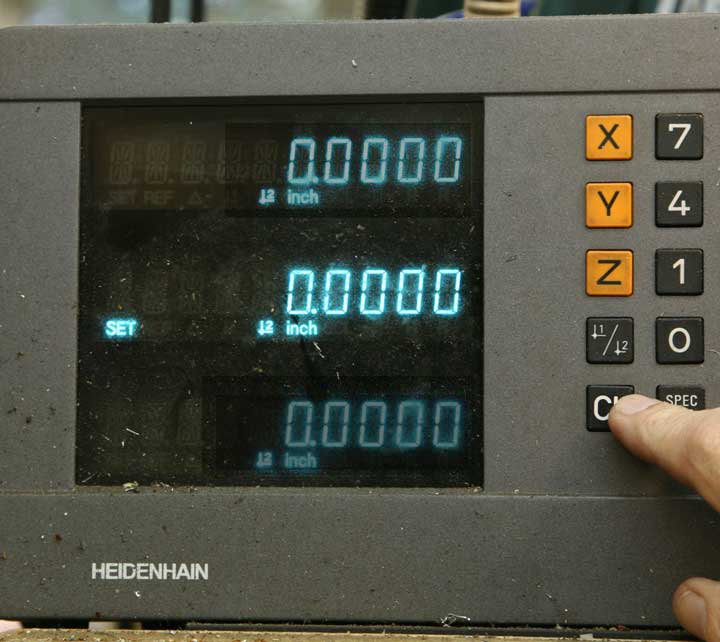
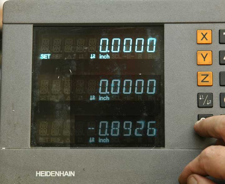
Leave the table in that position, and set the Y-axis of the DRO to zero.
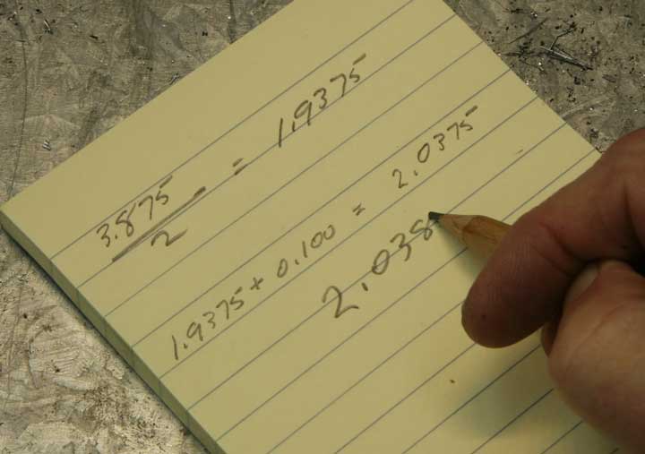
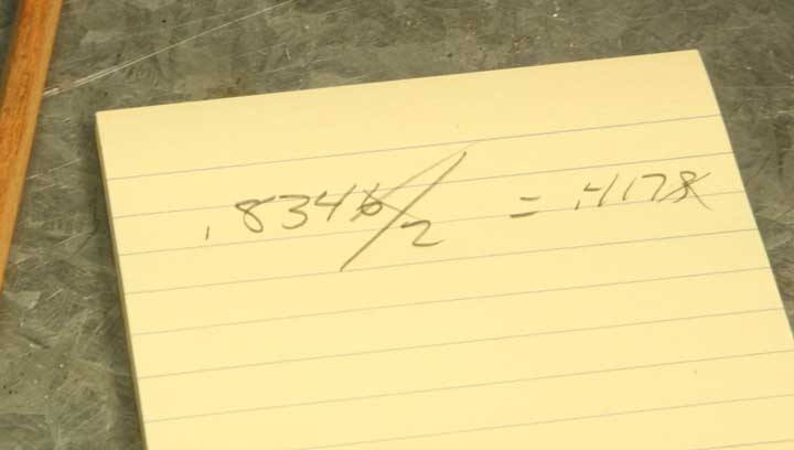
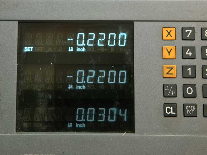
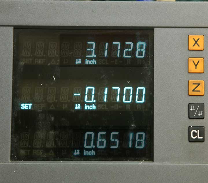
Now for a bit more calculating. The edge finder has a diameter of .200", so when it touches the work, the axis of the spindle is centered exactly .100" outboard of the work. In order to center the work, you need to add that amount to the distance from the edge to the center. In this calculation the distance doesn't work out to an even thousandth of an inch, so I rounded it off. DRO units often read out to fractions of a thousandth, but for most units, that decimal place isn't exactly reliable.
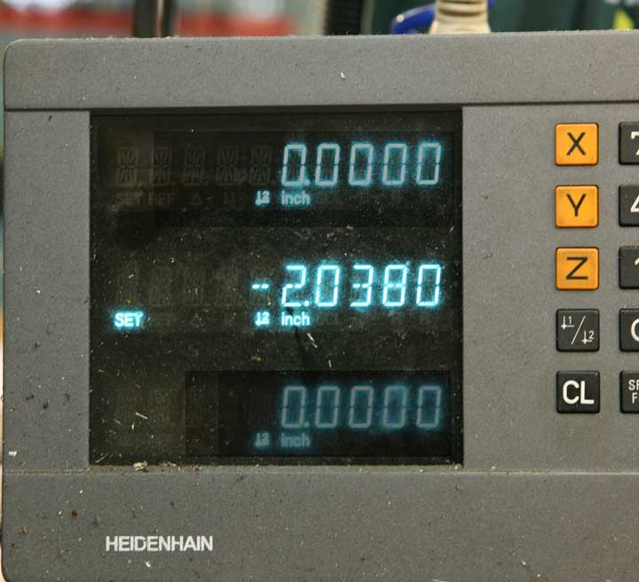
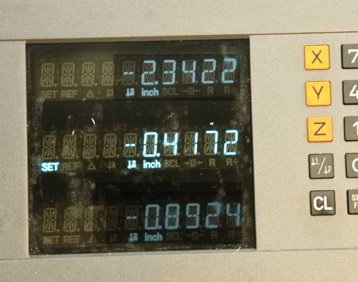
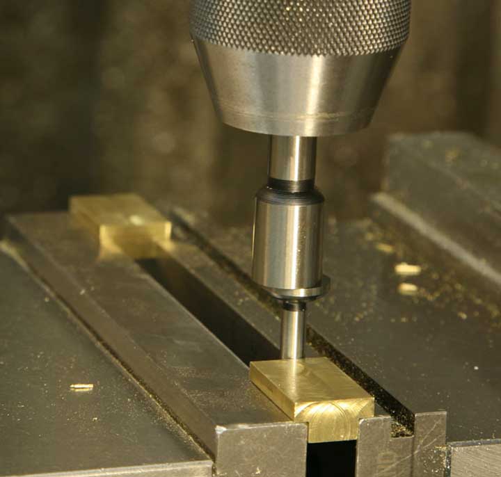
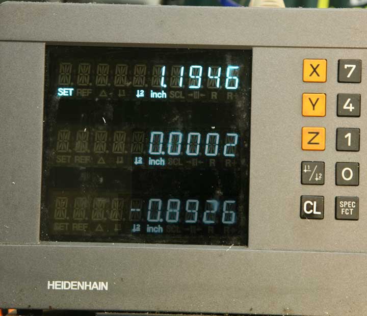
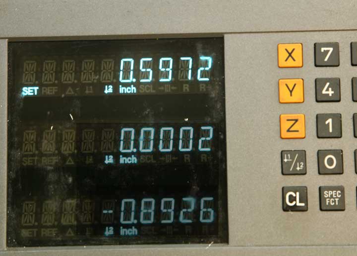
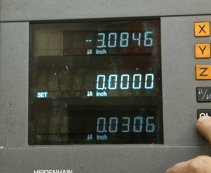
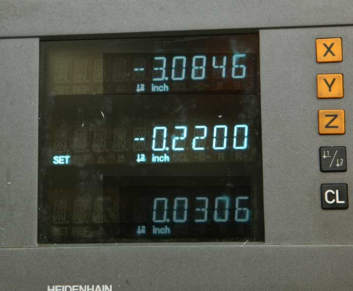
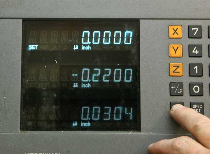
Raise the quill, and move the table Y-axis until it is centered according to your calculation.
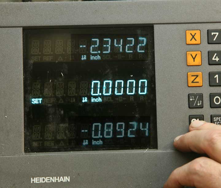
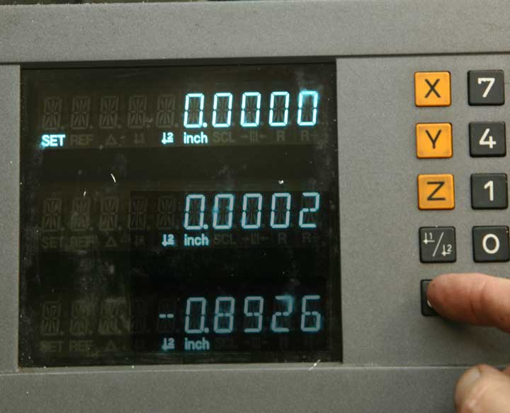
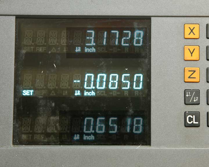
Then, set that reading to zero. Any time you want to return to center, you can move the Y-axis to the zero mark.
Because you'll be making a heavy cut along the X-axis, it's a good idea to lock the Y-axis so there won't be any unnecessary vibration.
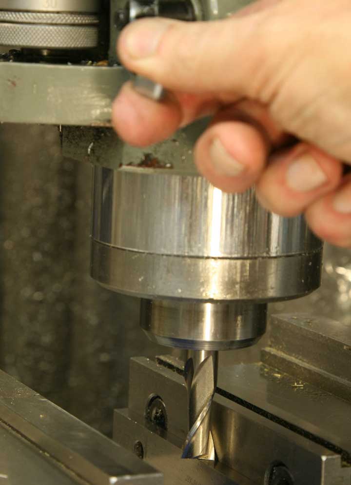
Mount the 3/8" end mill and bring the quill down to just touch the surface of the work piece. Lock the quill.
Set the knee dial to zero.
Lower the knee a little.
Move the X-axis to the right so the end mill clears the piece.
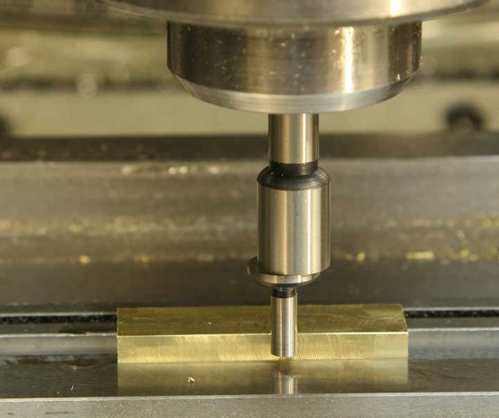
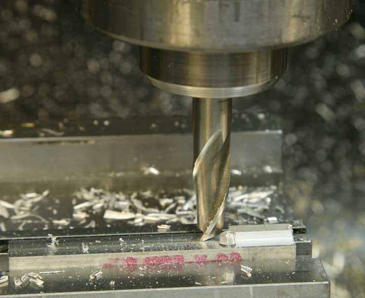
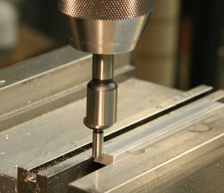
Raise the table to the zero point. Then, raise the table .300," which is the depth of the groove you'll cut.
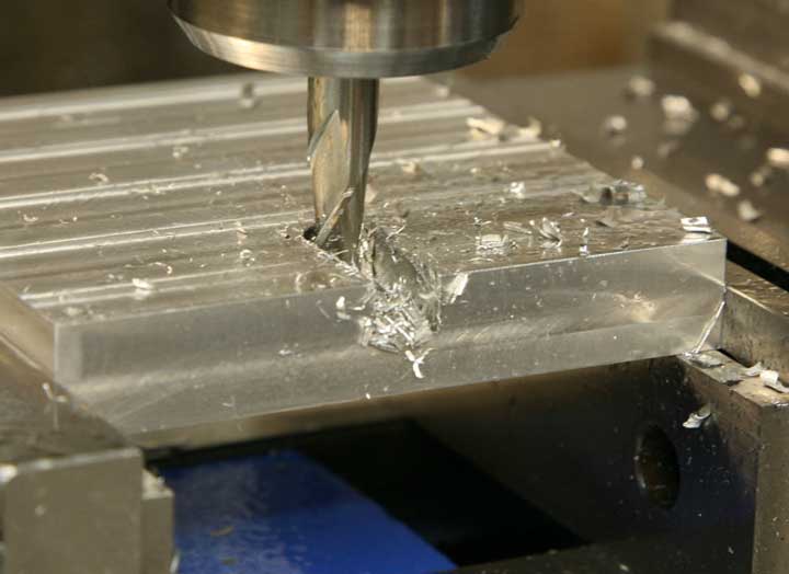
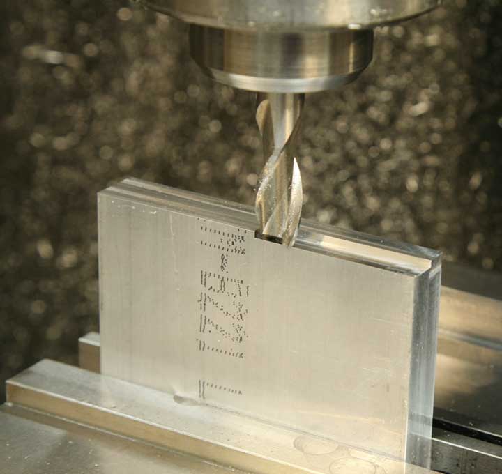
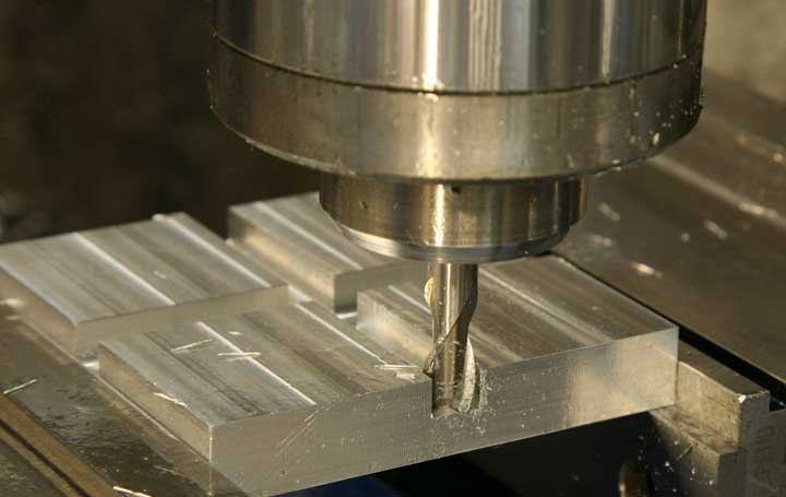
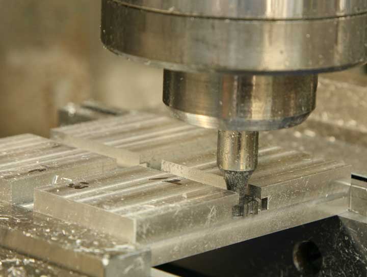
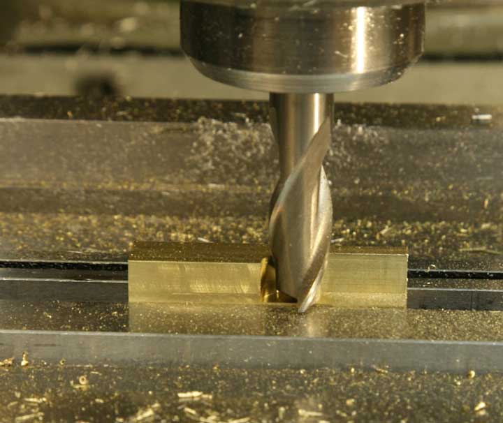
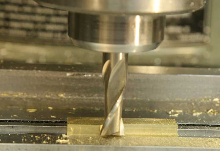
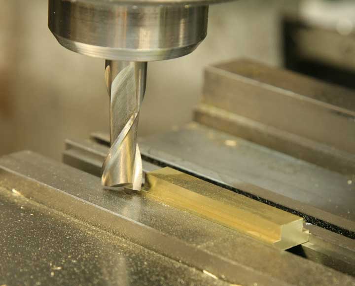
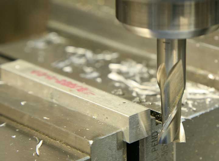
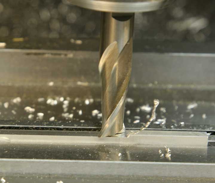
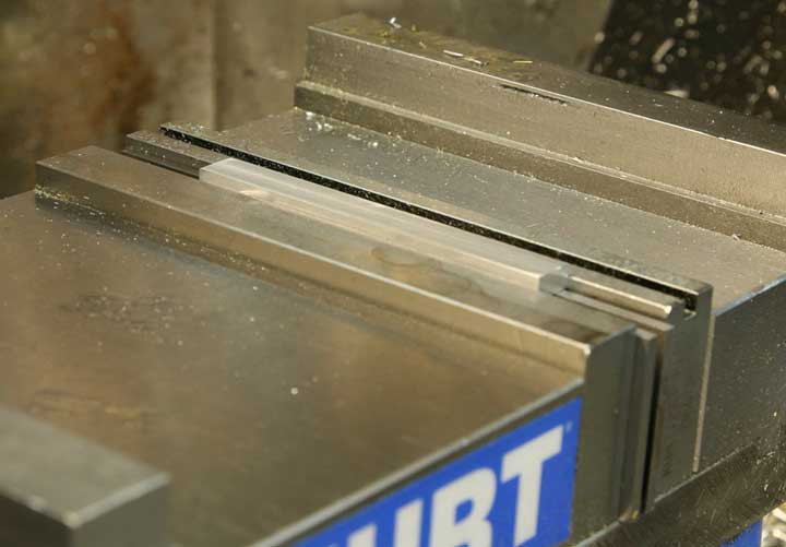
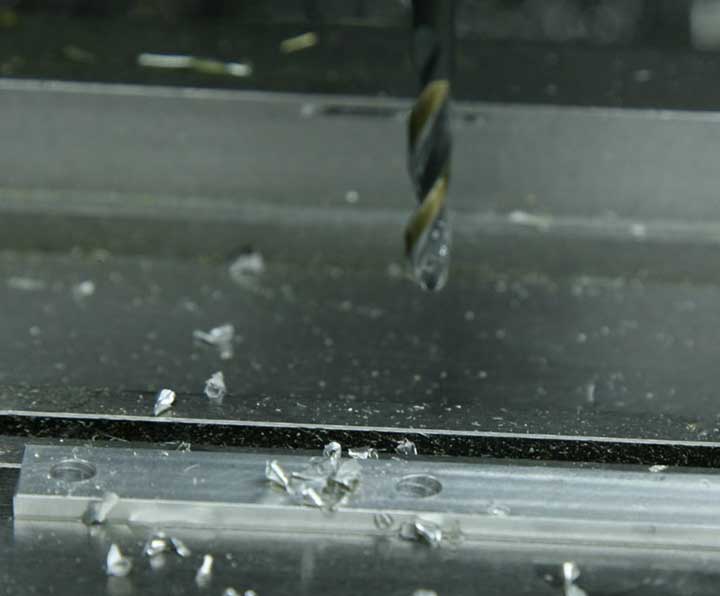
Taking it slow, and using some spray lubricant, cut through the piece from one end to the other. You should have a nice clean groove through the part when you're done.
Take the piece out of the vise, clean up and reclamp it after rotating it ninety degrees. Make a second groove through the piece. Now you have a pair of grooves .300" deep and .375" wide. Because you took the time to make the piece accurately square, each groove is centered nicely.
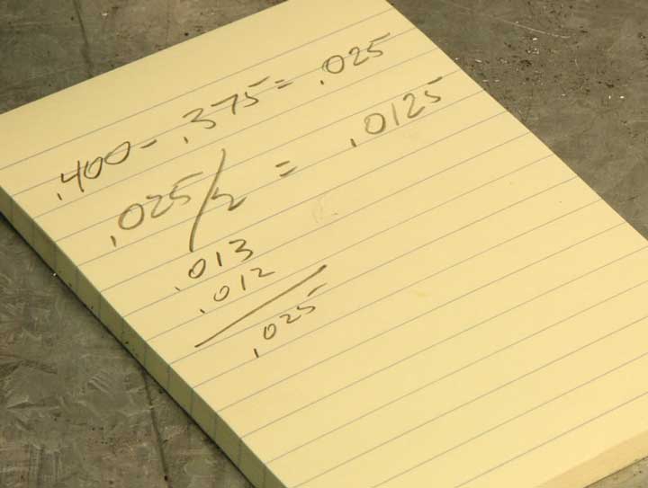
To widen the grooves to the final dimension of .400", you need to take a bit off each edge of the groove. This calculation results in a measurement that isn't easy to adjust using the DRO, so you can choose to take .012 off one edge and .013 off the other in order to get the exact dimension of .400.
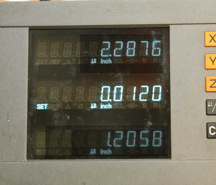
Leave the quill locked and, with the tool off to the right of the work, loosen the Y-axis lock. Move the Y-axis .012.
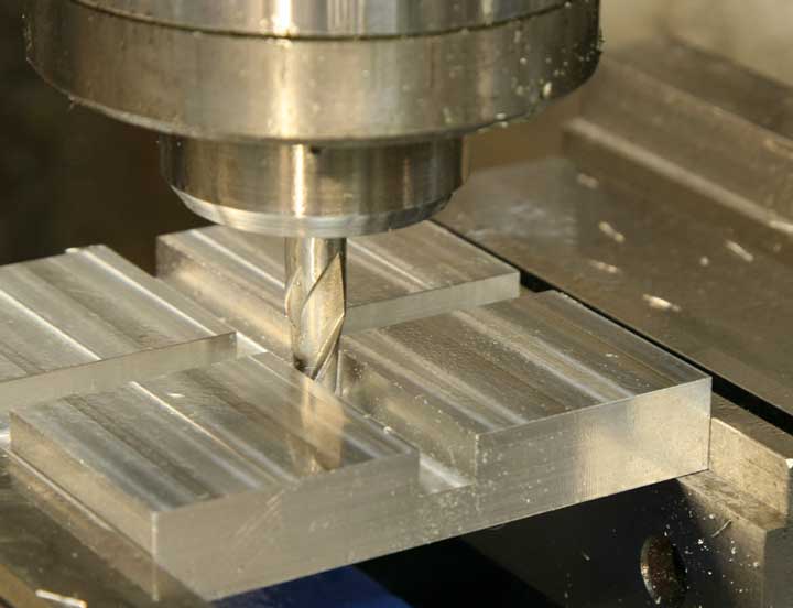
Take a nice clean climb cut across the front edge of the groove.
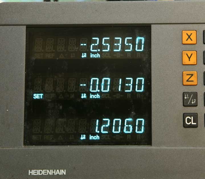
With the tool outboard on the left, move the Y-axis forward .013.
And, cut that amount off the back edge.
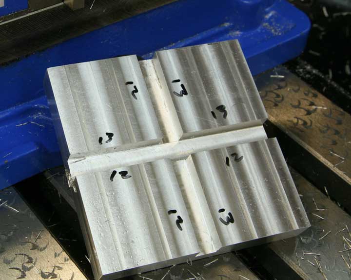
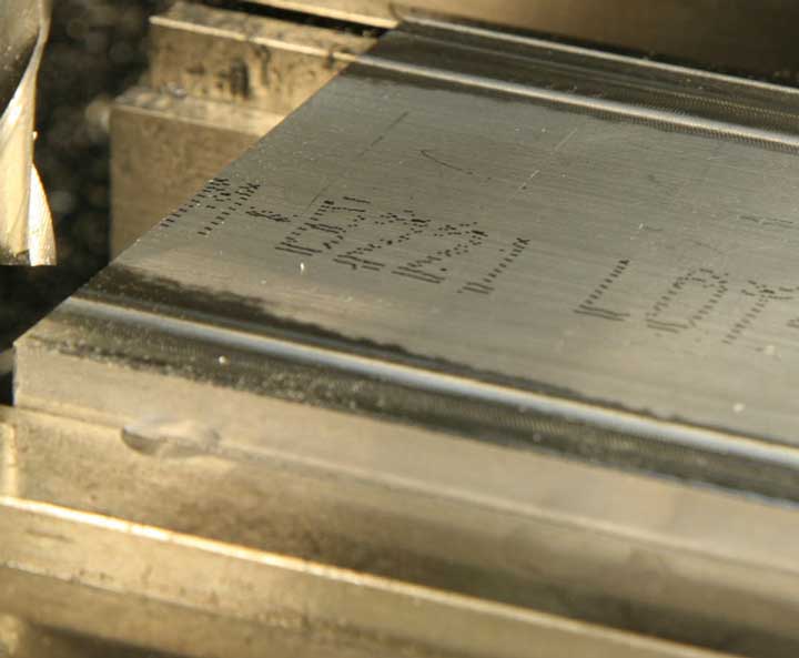
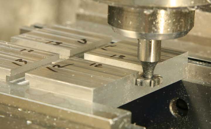
Before you go any further, mark the piece so you can be sure which edge was cut by which amount. This may seem a bit silly, but since the grooves are no longer centered, you could introduce an error when you make the bottom part of the "T-slot."
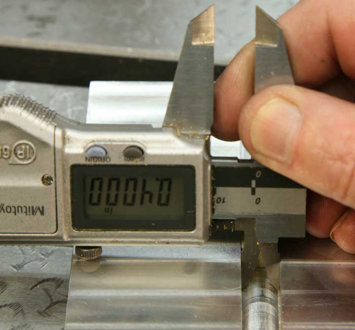
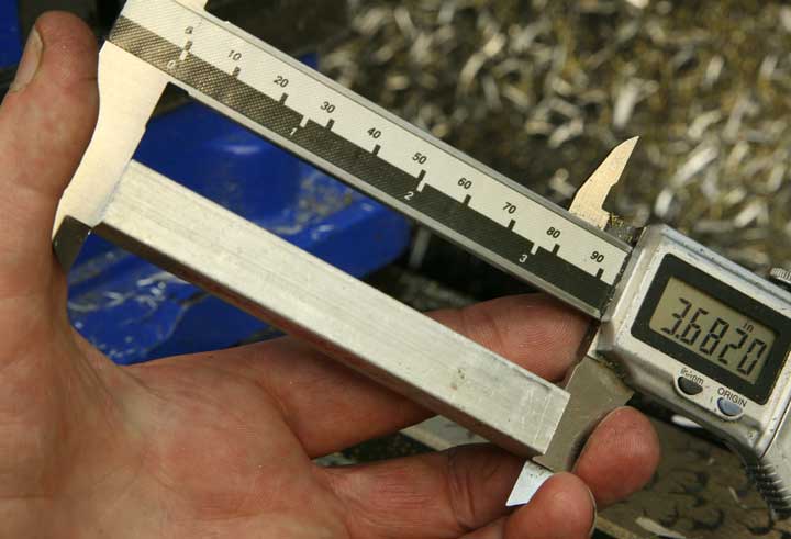
A quick check with the caliper will tell you how close you came to your goal so far.
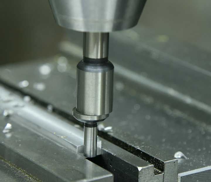
With the T-slot or Woodruff key cutter in the collet, you can set the depth of the cut exactly as you set the depth for the groove. Lower and lock the quill so the cutter is just touching the surface of the plate. Then set the zero on the Z-axis dial, lower the knee a little, move the x-axis to move the tool from above the piece, and raise the knee exactly .300.
Return the Y-axis to zero, and lock the Y-axis just as before.
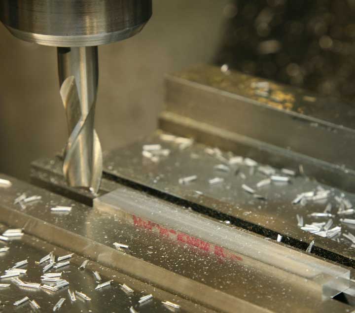
Again, using plenty of lubricant, make the T-slot cut through the length of each groove. The lube is likely to wash off all or part of your marks on the top, so be ready to renew them as you work!
Now, just to make the T-slot even with the original groove, and to clean up the tool marks, you'll want to climb cut each edge of the T-slot. Move the table away from you by .002.
Take a climb cut off that front edge - the one you cut by .012 when you made the groove.
And, repeat for the back edge, this time moving the table forward by .003 so you can make the cut at the back edge where you had removed .013" from the original groove.
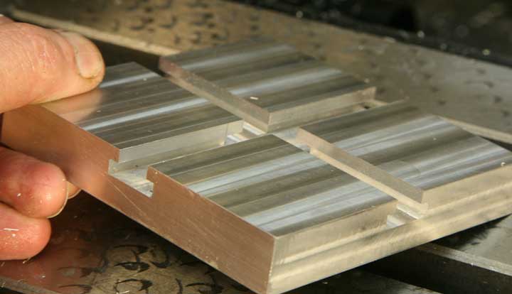
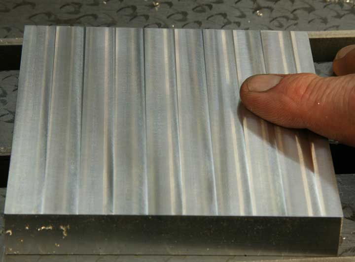
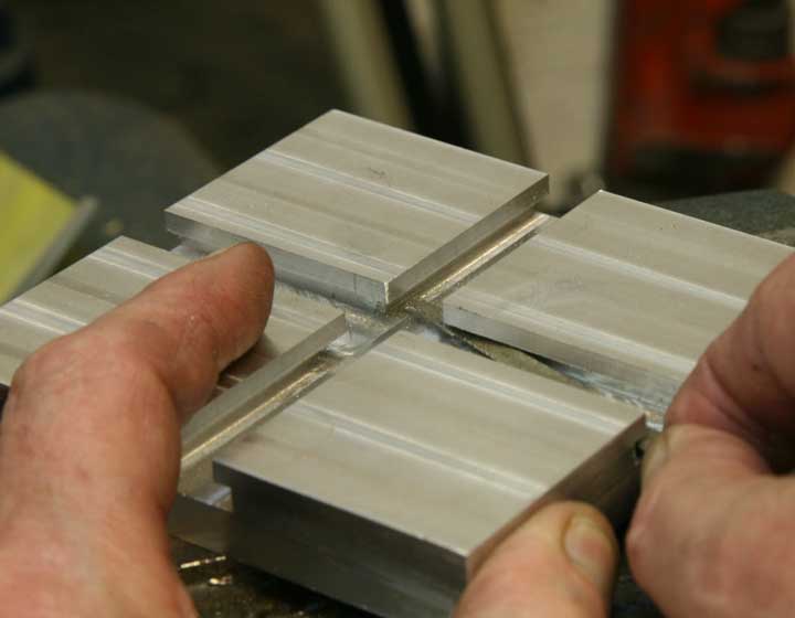
Well, that's it. Now you have a nice base for your two-slider, and it has clean, even T-slots at right angles.
In order to fit the sliders, you'll want to make accurate measurements of the slots in all dimensions.
It's no real problem if the measurements are not quite what you were aiming for as long as you use the actual dimensions for reference when you're making the sliders.
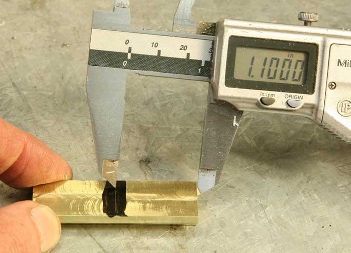
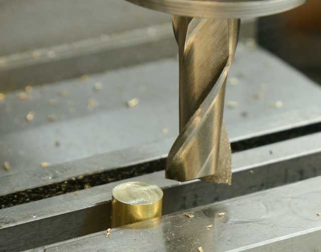
The sliders are brass, for easy machining, and smooth gliding in the aluminum T-slots. The sliders are to be 1" long, so it pays to start with a piece that's about 2.25". The finished sliders are short, so it's easier to make them as a single long piece to be cut in half after it is fitted to the slots.
This particular piece of brass is a bit wide, but that's no problem.
It's 1/2" thick, leaving just enough for cleanup and dimensioning to fit.
First, trim both ends nice and square, cutting as little off as possible. Grip the brass in the mill vise, supported with parallels.
Stand the piece on edge; clamp it down and mill one edge clean and flat. Whenever possible, it's a good idea to clamp small parts in the center of the vise so clamping pressure is more evenly distributed.
Flip the piece over and mill the other edge parallel and flat. Don't forget to file those corners so the piece will be easy to hold!
Lay the brass flat on the parallels and mill both faces flat.
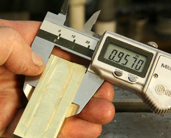
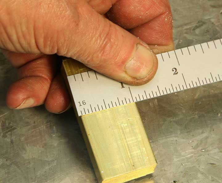
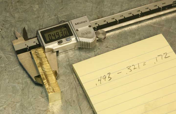
OK, more calculation. Measure the final width of the brass.
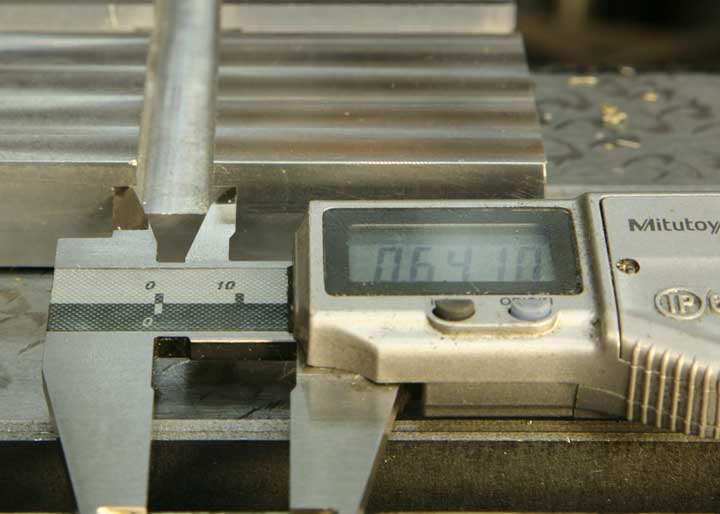
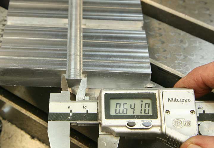
And, the width of the T-slot bottom.
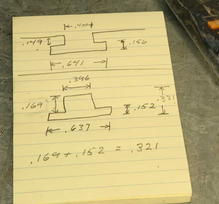
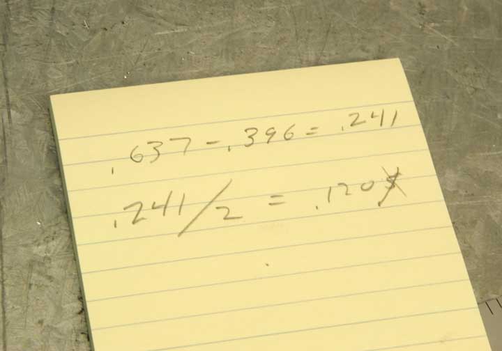
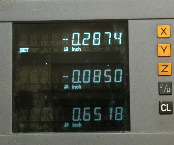
Here are my measurements. My T-slot has a width of .641 at the bottom, so I want my brass slider to be that same width MINUS .004" or so for easy sliding clearance. So, my slider should have a maximum width of .637 or possibly a tiny bit less. My brass was .957" wide, so subtracting the final width of .637, I know I need to take off exactly .320" to achieve the result I want.
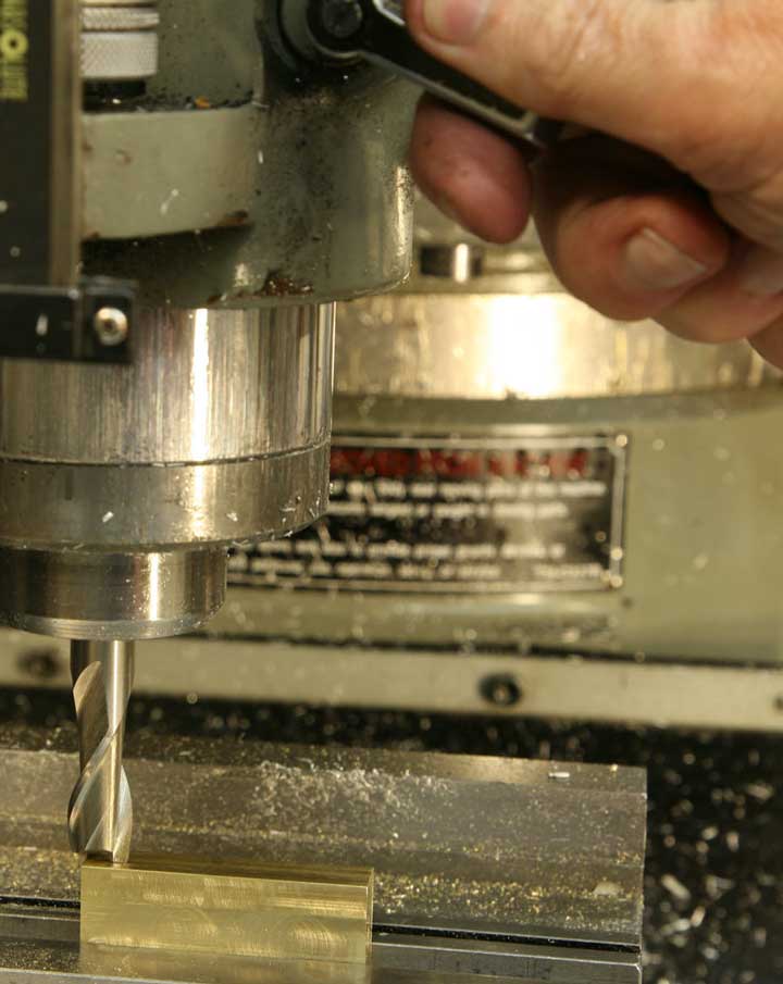
Touch the end mill to the work, lock the quill, set zero on the Z-axis dial, lower the knee just a bit and move the table so the bit is away from the brass piece.
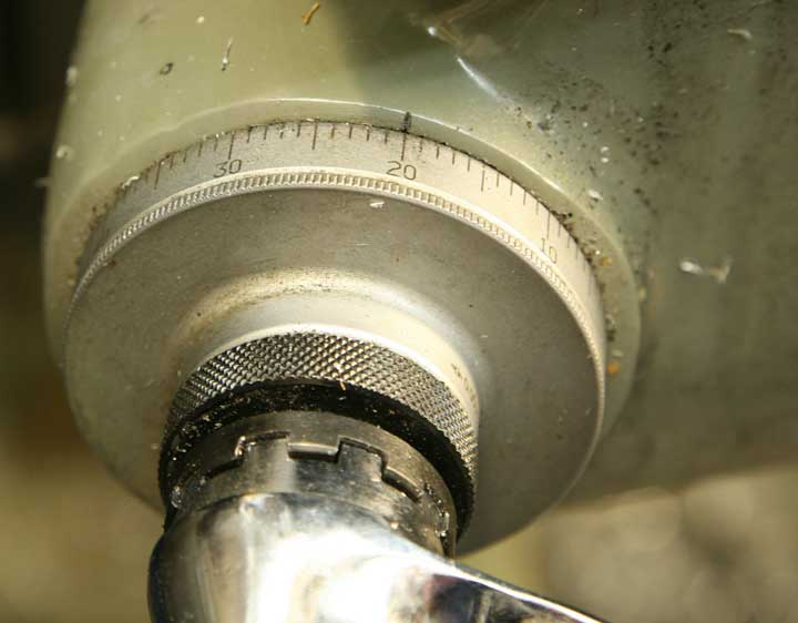
Return the Z-axis to zero and raise the knee by the amount you calculated - in my case that was .320, or three full revolutions plus .020.
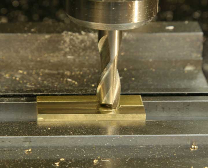
Make that cut across the brass just as you did the aluminum, climb cutting the front and back.
The slider should be .020" taller than the depth of the T-slot so that a portion will stick above, allowing clearance for the slider arm to move without scraping the surface of the base. In my case, the slot worked out to exactly .301" deep, so my slider should be .321" tall. Measuring the current thickness of the brass piece, calculate the amount you need to remove to make it .020" more than the depth of your T-slot.
Once again, touch the tool to the part, lock the quill, move the table to clear the tool, adjust and lock zero on the Z-axis dial.
Raise the knee by the dimension you calculated and cut that amount off the top of the brass piece.
Now it's time to make the brass piece into the T-shape that will fit the T-slots in the base. Using the edge finder, just touch the front edge until the bottom section kicks over. Don't hesitate to repeat the procedure as many times as necessary to be confident that you're getting an accurate reading.
Set the Y-axis DRO reading to zero.
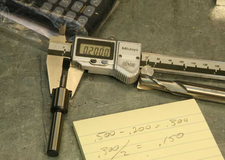
This time you'll be using the 1/2" end mill, and taking a precise cut in from the front edge of the part. In order to do that, you'll need to start with the end mill right at the front edge of the part. You could simply lower the end mill and move the table Y-axis until the end mill touches the part, and that would be pretty darn accurate if you're careful. An even more accurate method is to use the edge finder. Keeping in mind that the edge finder is .200" in diameter and the end mill is .500, you can easily calculate how far over you have to move the table once you find the edge with the edge finder. You can subtract half the diameter of the edge finder from half the diameter of the end mill, or, as I did here, you subtract the full diameter of the edge finder from the full diameter of the end mill and divide by two.
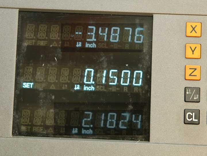
Either method produces the same result, namely .150" Once you get a good reading with the edge finder, move the table back away from the edge finder by .150"
Set the Y-axis reading to zero.
You now have the table set so the bit will be aligned right at the edge of the part. Remove the edge finder and install the 1/2" end mill.
Subtract the final dimension of the narrow portion of the slider from the current dimension, and divide by two. If it comes out to an uneven number of thousandths, round downward because you want a sliding fit with no binding, so it's better to be just a taste undersize than oversize.
Now to set the depth of the cut for this important notch. This time instead of working from the top, try working from the bottom of the part. Bring the bit down to just touch the top of the parallel, which, of course, is even with the bottom of the brass piece.
Set zero on the knee dial.
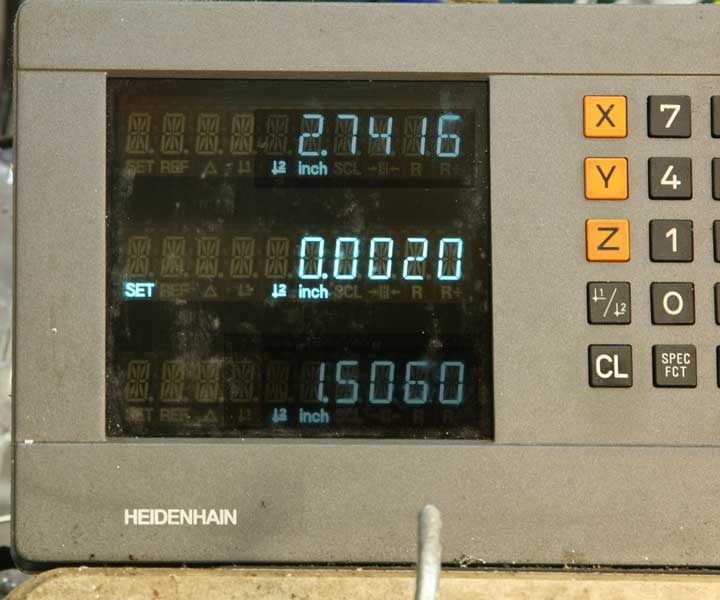
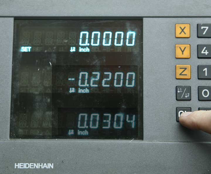
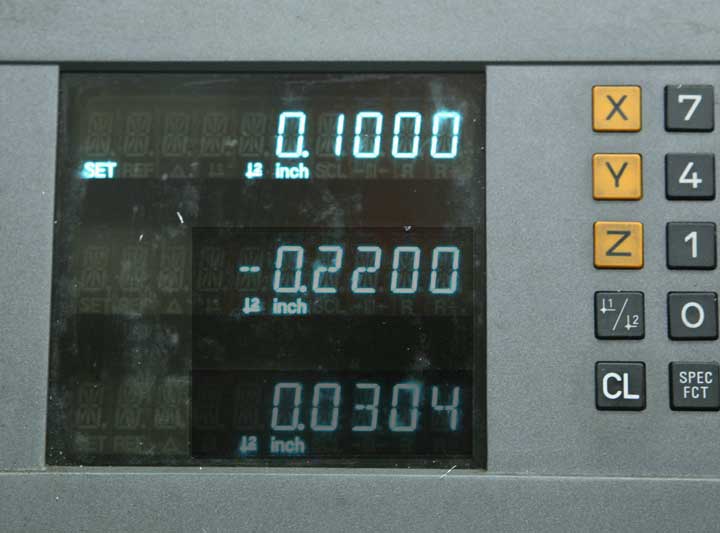
And lower the table by the final dimension of the slider. When lowering the table you have to be careful to count backward from zero because you're going opposite the direction of the numbering. It's not that difficult. Here, I've set my final dimension of .152" or .004 less than my final T-slot bottom height. The reading is 48 (100 minus 52)
Move the Y-axis to .120 as calculated above, and lock the Y-axis
Now, take a nice climb cut the length of the part.
Take the brass out, turn it around and make a similar cut across the other edge.
With any luck, you now have a nice sliding fit in the T-slots. If the piece binds, check for burs and rough edges before trying to make any adjustments in dimension. File all the corner edges, and you should have a good fit. If you do need to take some material off, be quite careful to make sure you can see where the piece binds before putting it back on the mill to cut it.
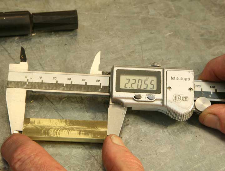
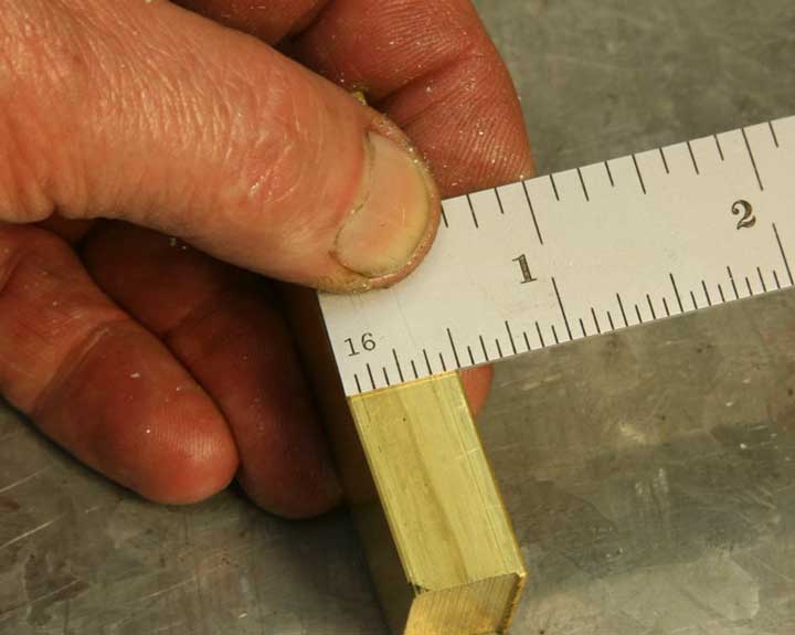
Measure the length of the slider.
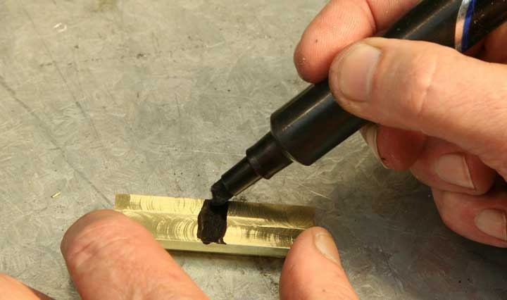
Make a nice black mark in the middle of the brass
Set your caliper to half the length, and use it to scribe a nice sharp line.
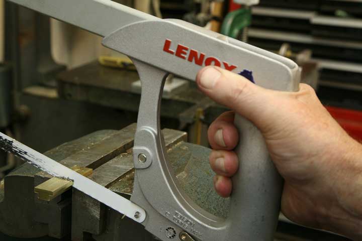
You'll only have to be slightly careful to cut this in half, leaving two pieces a bit over 1" long.
Here's an easy way to make both pieces exactly one inch long. Using a single parallel that will allow about 3/4" to 7/8" of clamping space above it, lower the quill until the 1/2" end mill just touches the parallel. Lock the quill
Set zero on the Z-axis dial.
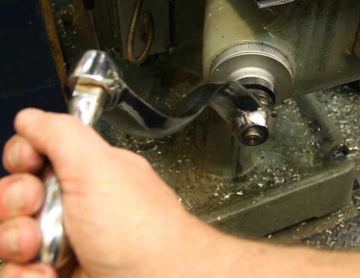
Lower the z-axis exactly one inch. On most mills, that will be ten full revolutions.
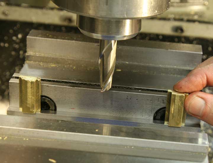
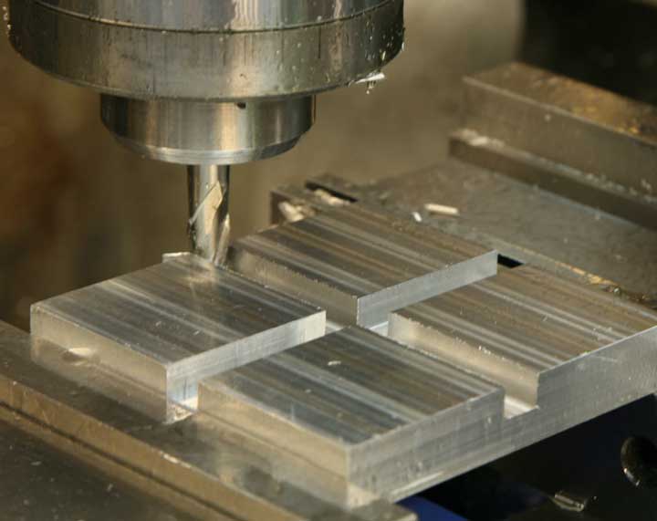
Place the two brass parts in the vise, balancing their square cut ends on the parallel. All vise jaws move slightly out of alignment when parts are clamped only on one end, and you can take advantage of this by placing each piece near the ends of the vise jaws. Then when the vise is tightened, it will grip both pieces solidly. If you were to clamp them next to each other it's very likely that one would be tight and the other loose enough to shift position during the milling process.
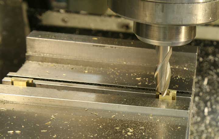
Mill the tops right off.
You'll have nice cut ends and accurate length.
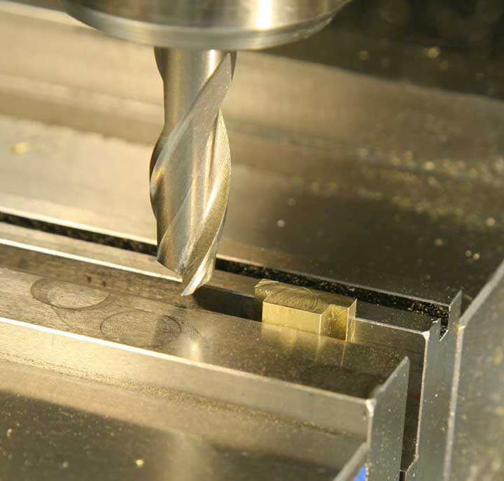
The next operation is to drill and tap screw holes in the centers of the parts. This time you'll clamp both in place to keep them solid, but you'll work only on one at a time. The idea is to "index" the part right at the edge of the vise, so you can measure for only one, but cut both exactly the same. Turning the pieces upside down and gripping them by the small section you can slide one over to the right, and position it exactly at the edge of the vise, using a parallel as a guide. Hold the piece against the parallel as you tighten the vise. Make sure you hold it down against the vise jaw top as you do so.
You did file off all the burs left by the previous operation, and you cleaned all the relevant surfaces, didn't you? Right. Now it's time to use the edge finder in a slightly different way to find the center of the part. This happens to be my favorite method, finding both edges rather than finding one and measuring the part. First, find the front edge as before.
Then, set the Y-axis on zero.
Now, find the back edge.
Note the Y-axis reading.
Divide that in half. Here I've eliminated the "tenths" because that kind of accuracy is beyond our scope.
Raise the quill to clear the edge finder, and move the Y-axis to the calculated dimension.
Set zero on the Y-axis of the DRO. Now, anytime you want to return to center, just go to "0."
Now, repeat the process, this time with the X-axis. Find the right edge.
Set the DRO to zero on the X-axis.
Find the left edge.
Note the X-axis reading
Divide by 2.
Raise the quill, move to the calculated dimension.
Set the X-axis to zero. Wow, now you can accurately find the center of the part by simply moving the X and Y handles until you reach zero on both DRO axis readings. AND, even better, you can do it again with the other part as long as you index it against the side of the vise. Imagine the time and effort you'd be saving if you had a hundred of these little buggers to make.
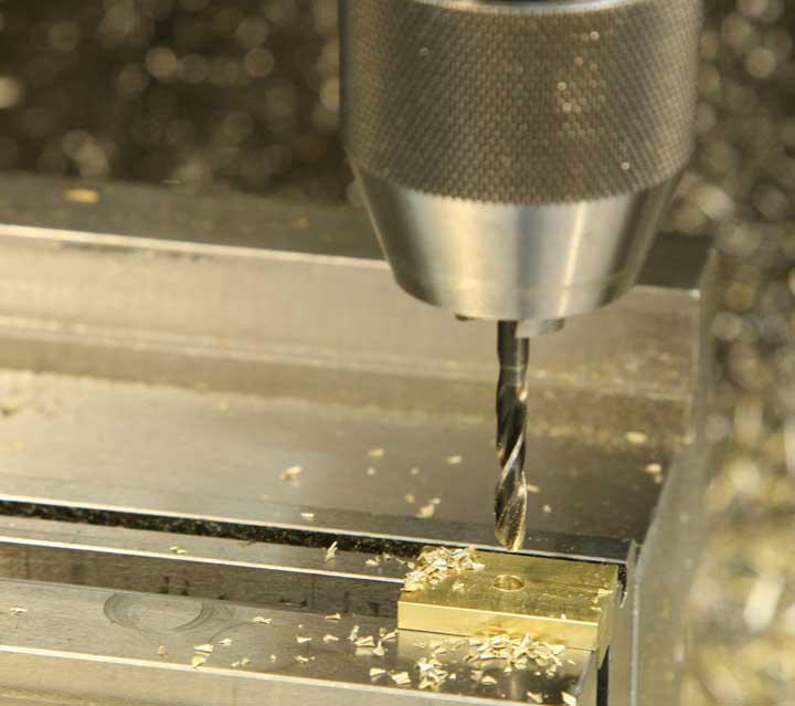
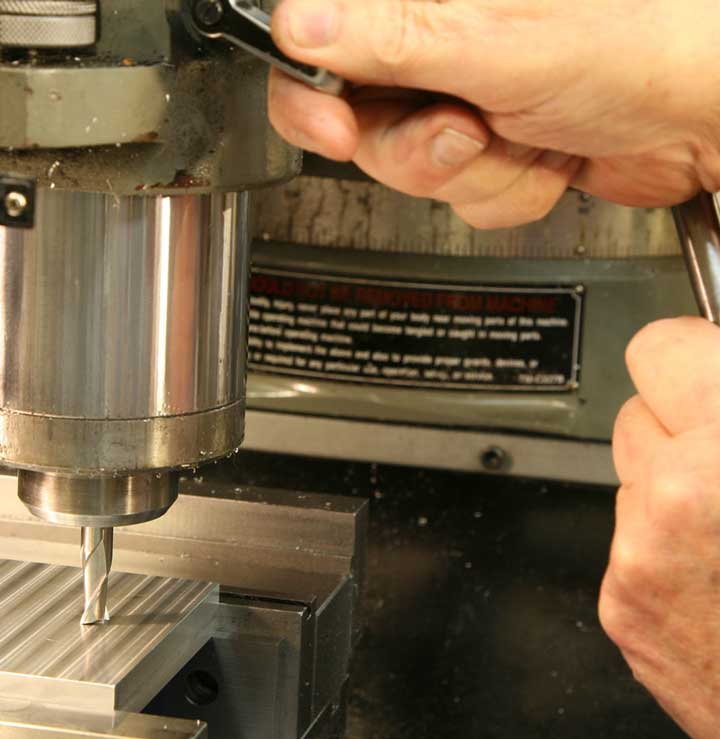
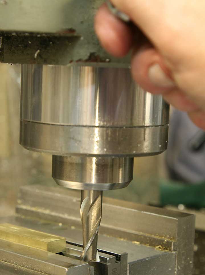
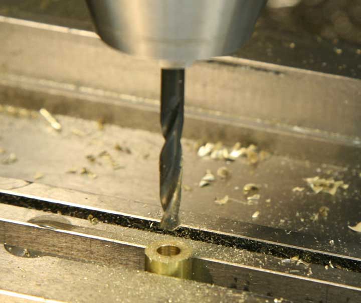
Put the drill chuck in the spindle, and drill a hole on center (X and Y at zero, yes?) with a #21 drill.
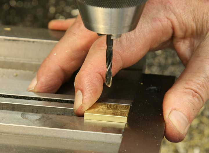
Quick, switch parts, index the new one against the vise jaw end, and drill it the same way.
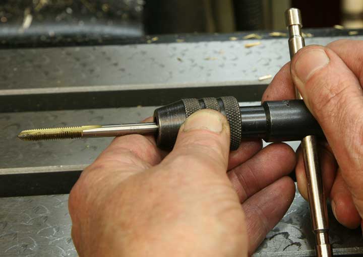
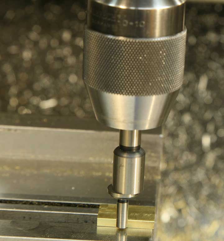
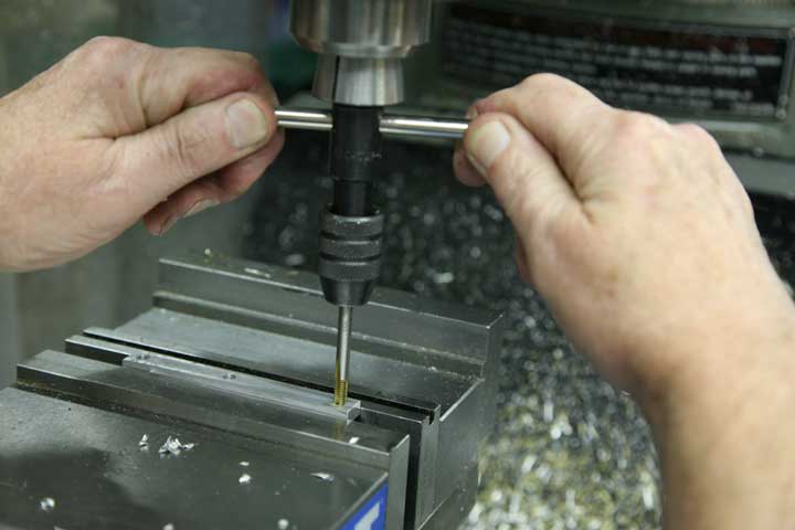
Load up the tap handle with a 10-32 spiral point tap. Also known as a "gun tap" because it "shoots" the chips ahead as it cuts, this is the most efficient tap for threading holes that go all the way through a piece. It's only natural to think that if you have a nice straight hole, the tap will follow the hole and make nice straight threads. Well, sorry to say, it just doesn't work that way. In order to get straight threads, you need to have a mechanical way to align the tap. Fortunately, the milling machine can help.
This is a technique you use with the machine turned OFF. First, stick the end of the tap up into a collet of the appropriate size, and shove the collet up into the quill, but don't tighten it there.
Then, return to zero to center the tap over the hole.
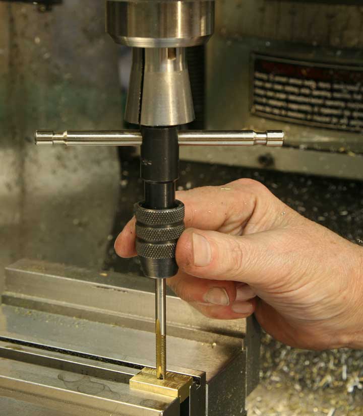
Stick the tap into the hole
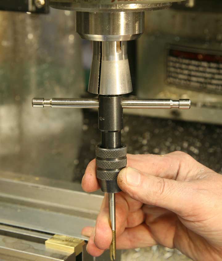
And, lower the quill almost to the lowest it will go. Lock the quill.
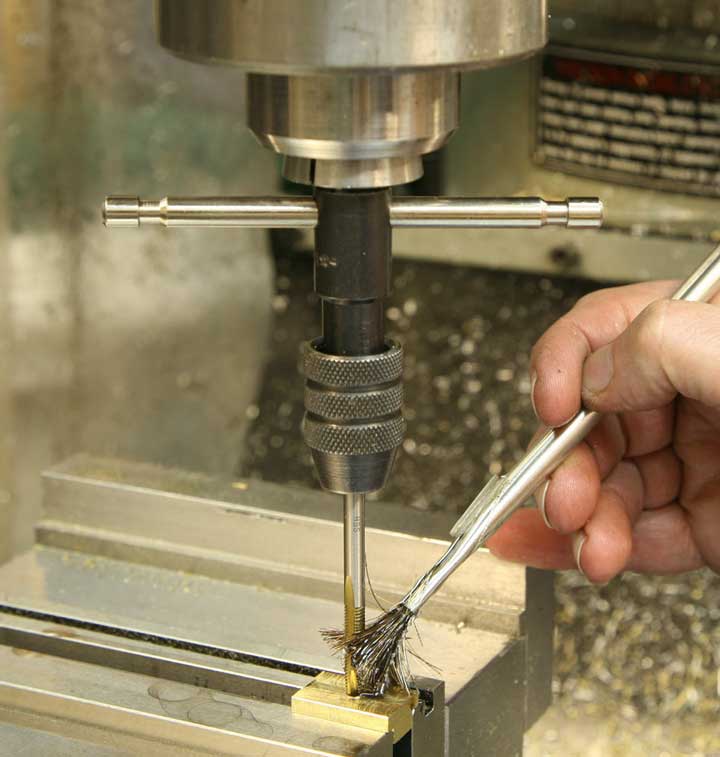
Apply a bit of tapping lubricant.
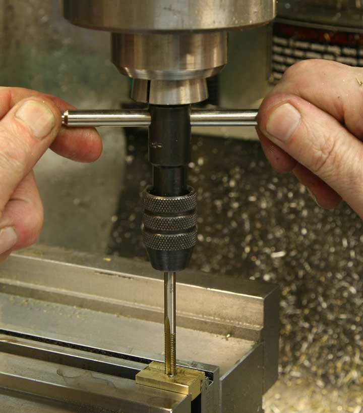
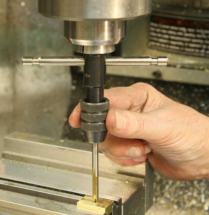
Proceed to tap the hole, with absolute assurance that the tap will be guided straight and true.
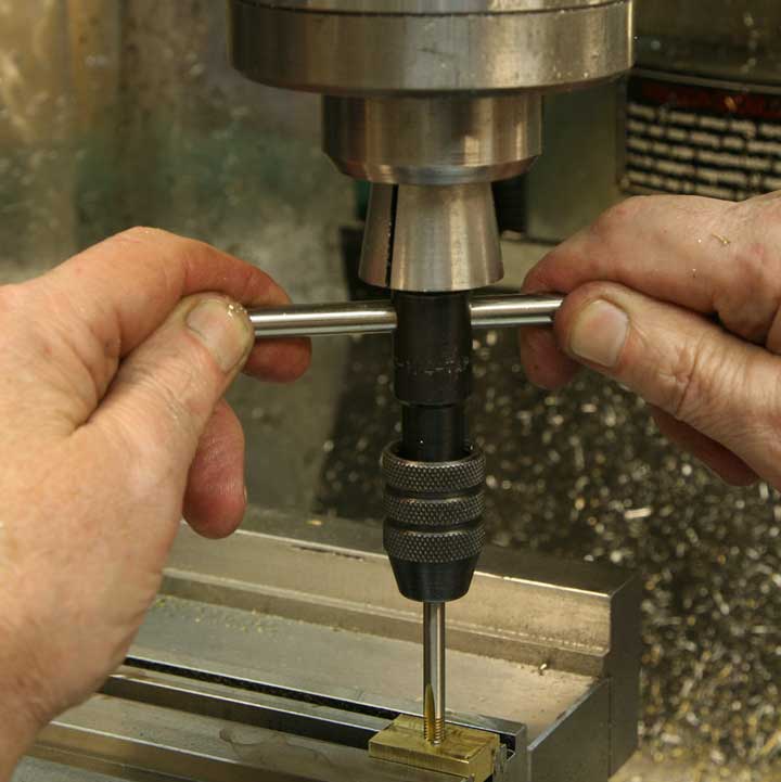
As you tap, the collet will be drawn lower, but it will continue to do its job, nicely guiding the process.
If you haven't already, go ahead and use a small file to "break" the corners of the slots and remove any leftover burs or roughness.
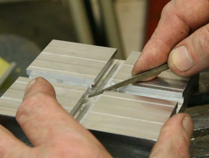
All corner edges will need a bit of attention.
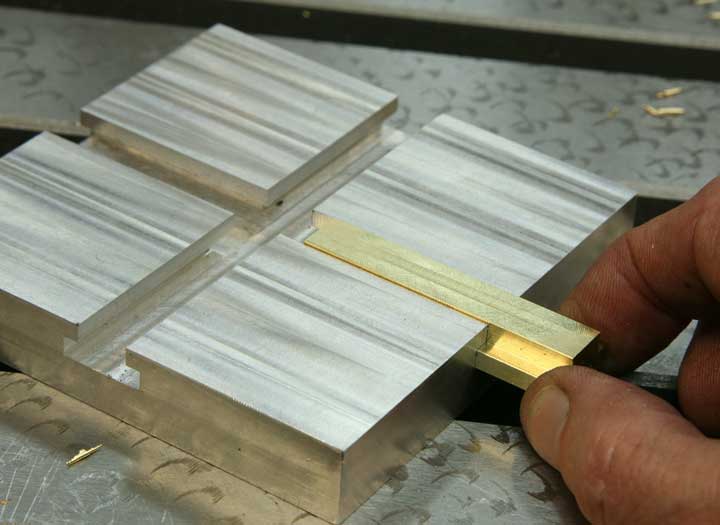
Same goes for the sliders. Stick the sliders in the slots, and run them back and forth past the intersection. If they bump as they go past the junction, give their corners a bit more relief.
The handle is aluminum, and, just like the other parts, it will need to be trued up before use.
Trim the ends first.
You'll want the handle to be long enough to crank the mechanism nicely, but not so long that it gets in the way of life in general. Something between 3.5 and 4 inches seems good to me, and I settled on this length, which is how my piece came out when I cleaned up the ends.
More milling, first the top edge. The piece is supported on parallels, of course, so everything will come out even.
Then, flipping it over, the bottom, and setting the depth of the cut as in earlier processes, trimming it to the final dimension.
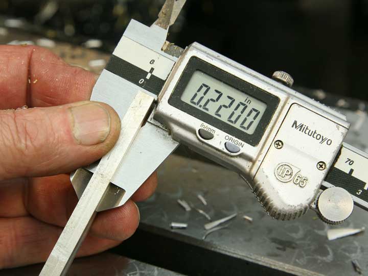
I chose .220, for a pleasing look. And, it's a nice round number, too.
Same deal for the opposite edges. First trimming for straightness, then cutting to dimension.
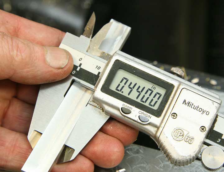
I like the idea of a 2x4, so I chose .440 for the width.
Now, with the piece in the vise, supported as usual with the parallels, you'll want to drill and tap some holes. But you definitely do NOT want to drill into the parallels.
So, with the vise tightened, you can remove the parallels, and, if you're at all reasonable about downward forces, the part will hold very well where it is.
Here we go again. Find the edge. But this time, let's find center in a slightly different way.
Set the Y-axis to zero. Raise the quill to clear the tool.
Move inboard half the diameter of the edge finder.
Set zero again.
Now, move inboard half the width of the part, which measures .440. This way is easy, yes?
Lock the Y-axis
Now find the left edge of the part.

Set the X-axis to zero.
Raise quill, move to half the diameter of the edge finder.
Set the X-axis to zero again
Move the X-axis the same distance as you moved the Y-axis. That way, you'll have a center point near the end of the part.
Set the X-axis to zero once again. Now, you can use this reference point to locate a second hole.
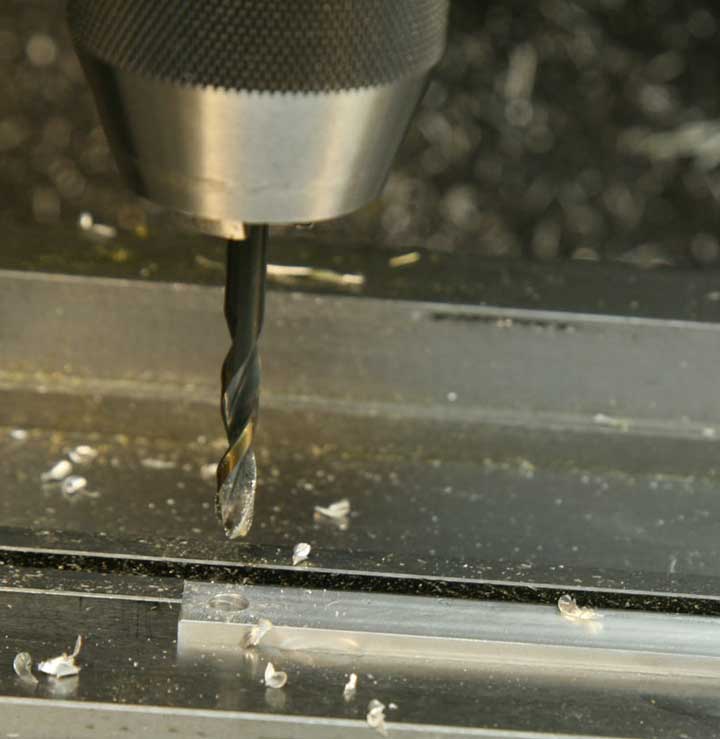
Drill through the part with #11 drill. That's the standard clearance drill for a 10-32 bolt.
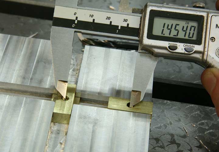
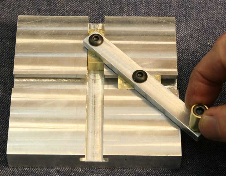
Position one of the sliders in the center of the slot and the other right at the end of the opposing slot. Measure the center-to-center distance between the threaded holes. While there are methods for making very accurate measurements, this job only requires "eyeball accuracy," so you can simply position the points of the caliper about in the middle of each hole.
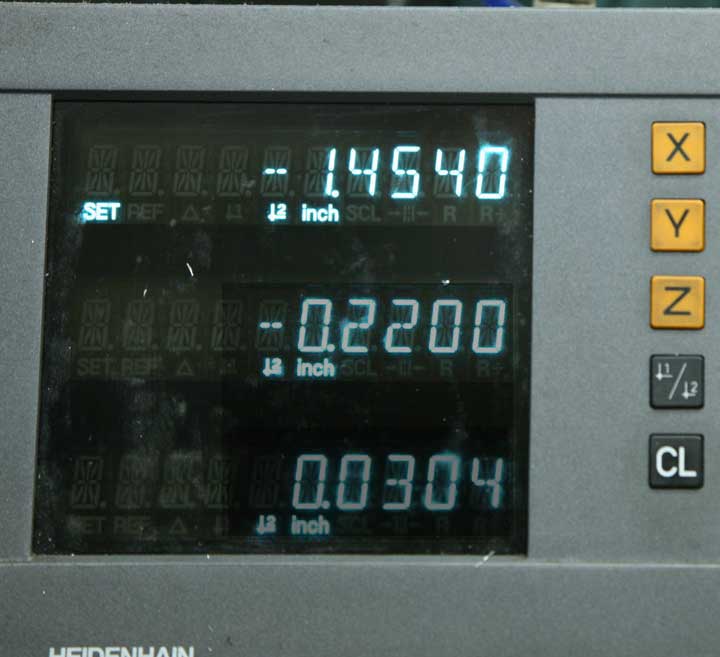
Move the mill table to the left by that same measurement, as read on the X-axis of the DRO.
Drill the second bolt clearance hole with the #11 drill.
Find the right end of the part with the edge finder.
Set zero on the X-axis
Raise the quill, move toward the part by half the diameter of the edge finder.
Set zero again.
And, move the table to the right by .220, just as you did at the other end.
Drill with the #21 drill, and thread the hole as you did when you threaded the sliders, using the quill as a guide for the tap.
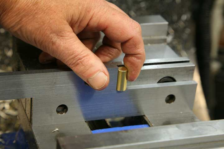
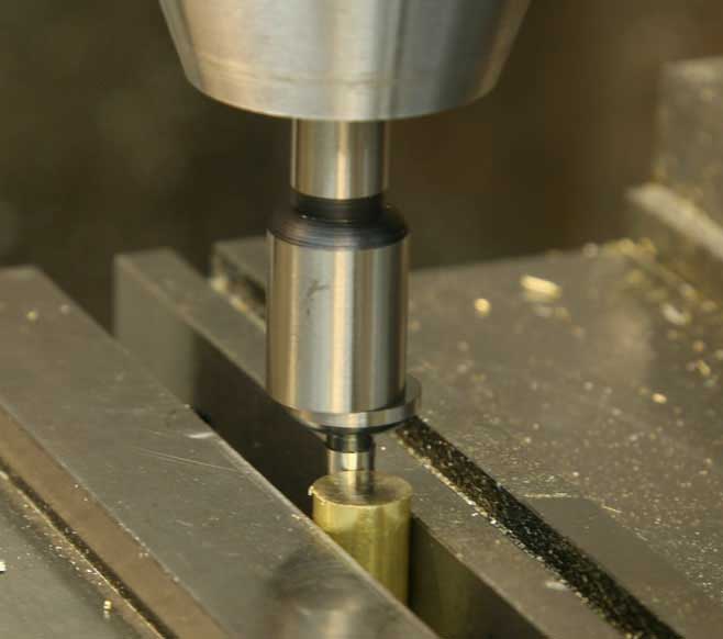
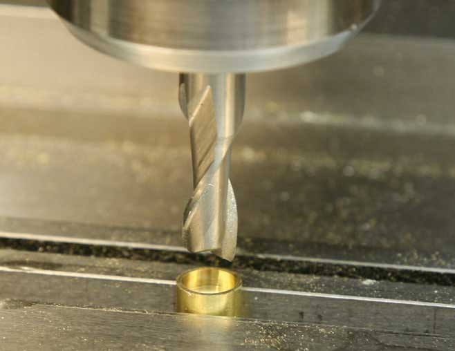
Making the little handle seems like it would be a natural job for the lathe, and so it would. But, this is an exercise in using the mill, so here's one approach that works pretty well. You'll start with a short section of 3/8" diameter brass rod. Stand the piece up on a parallel, and, using a second parallel as a guide, hold it vertically as you bring the vise jaw up nice and tight.
Take a light cut off the top with the 1/2" end mill. Turn the piece over, clamp it the same way, and mill off a bit of the top once again.
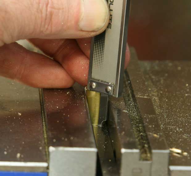
You can use the depth gauge on the caliper to judge the length, and this time, instead of measuring and calculating, just try "sneaking up" on the measurement, taking a bit at a time.
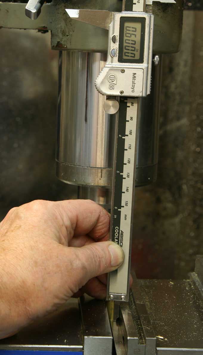
The precise length isn't critical, but it's always a good idea to try for precision, so take it slow and you should be able to come up very close to the ideal length of .600"
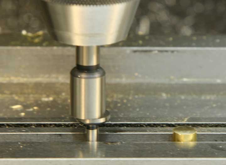
Now, to find the center of that little piece to drill through it. First, don't forget to take the parallel out from beneath the part so you don't drill into that piece of precision measuring equipment. Rather than finding the front edge of the part, use the edge finder to find the front jaw of the vise on the inside.
Set zero on the Y-axis of the DRO.
Find the inside edge of the back jaw of the vise.
Note the reading on the Y-axis.
Move the table along the Y-axis, and you'll be precisely centered between the vise jaws, and consequently, centered on the part.
Lock the Y-axis.
Now, since you are locked precisely on center, if you move the table to the left, you'll touch the exact center of the circumference of the brass rod. Find that edge.
Zero the X-axis of the DRO. Find the right edge and note the reading.
Move the table until the X-axis reading is half that measurement.
This time, zero out the reading, because you'll have to move the table back and forth to change bits.
Install the drill chuck, bring the table over to the zero on the x-axis, and drill the #11 bolt clearance hole.
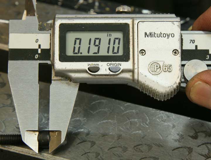
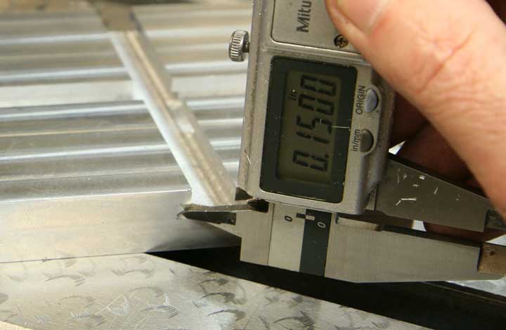
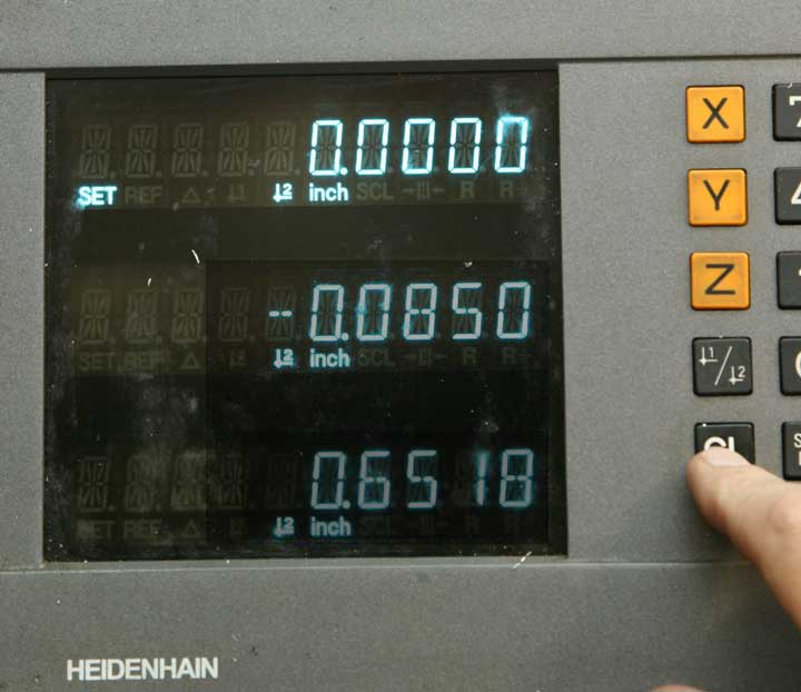
Measure the depth of the bolt head, so you'll know how deep to countersink the bolt into the brass rod.
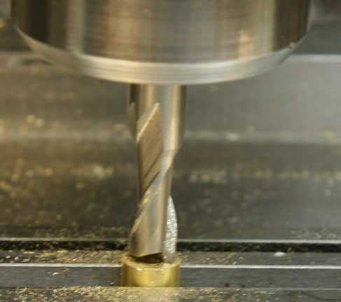
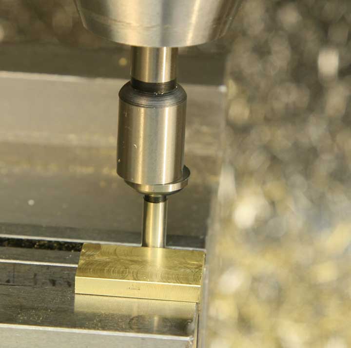
Install the 5/16" diameter end mill in a collet, bring the table over to zero on the X-axis, and lower the quill until the end mill just touches the surface of the brass.
Set zero on the Z-axis dial.
With the mill running, slowly crank the knee upward until you reach the measurement you made of the countersink depth.
In this case, it's .191"
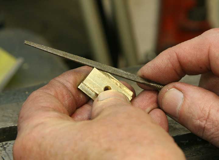
You should have a nice looking, centered and countersunk bolt hole.
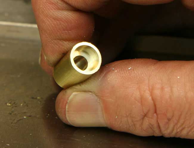
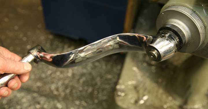
Here's the finished brass handle.
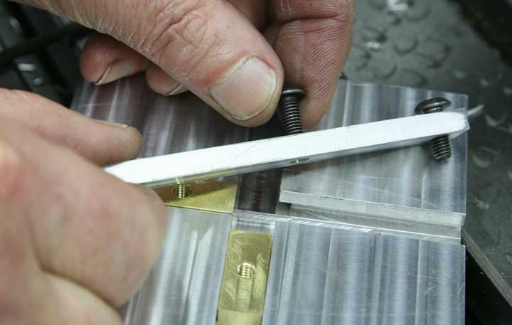
The only thing left now is assembly. Make sure you've cleaned off any burs or rough edges from all that milling and drilling, and stick the two button head cap screws through the clearance holes in the arm.
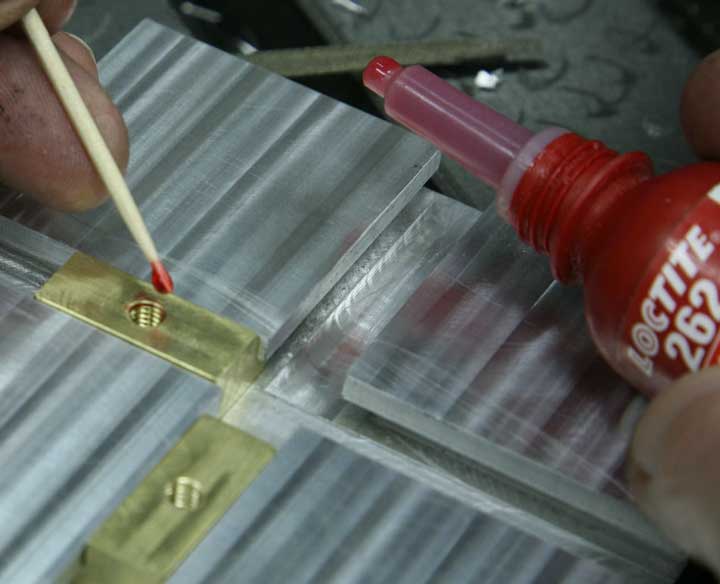
To avoid seizing the pieces together, you need to be careful with the application of thread locking compound. Use a toothpick to apply a small drop inside the threads of the brass sliders, and screw the button head screws in place. Bring them up fairly tight, and then back them off until the sliders just move freely without being really loose and sloppy.
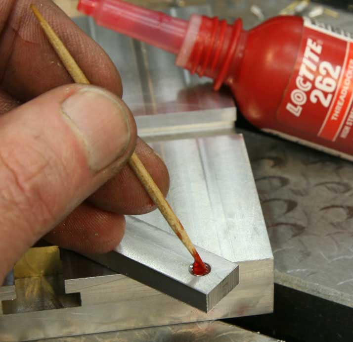
Same for the swivel handle. A small drop of thread locking compound on the inside threads only. Adding extra compound to the external thread of the screw may seem like a good idea, but there's always the possibility that it will leak out between the brass and aluminum parts, so try to avoid that temptation.
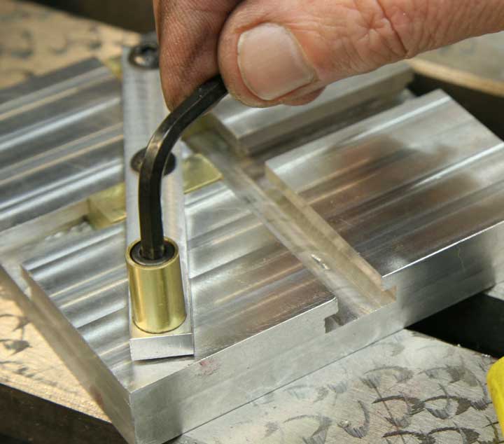
Screw down the bolt, back it off until the handle rotates freely. Now, avoid the temptation to operate the slider for while so the thread locker can do its job, which is to make sure the bolts don't loosen or tighten when the handle is cranked.
Congratulations. Now you have a cute little gizmo with virtually no practical use. But it's fun to show off. . .