
"Bridge Mill"
Adventures in metalwork, or how I made my "Bridge Mill"
In the last two years I've written hundreds of pages about instrument repair, and I've really gotten used to taking photos of my work in progress. So, as I put together this bridge routing fixture, I couldn't resist composing a small documentary of the work.
I do all my luthier type activity in the back room at Gryphon Stringed Instruments, but when it comes to tooling, I usually work in my garage at home, where I have a variety of power tools that aren't compatible with a retail environment. This is one of those "at-home-in-spare-time-jobs."
I present this material more as a view of how I go about tooling, rather than a detailed "how-to" article, for a number of reasons. First, I hope to illustrate how I, a woodworker, manage to make simple tools without being a machinist. Second, I chose an expensive way to go because of my limitations (time, tools, and machine skill) which I don't necessarily recommend. Third, I hope to encourage other wood-bound luthiers to consider working out their fantasies in tooling.
For many years I've wanted a very solid, precision routing fixture for guitar bridge saddles. I can't count the number of saddle slots I've routed in new bridges, or in old ones for intonation correction or pickup installation. I finally retired my 20 year old Dremel, and for the last year have been fighting the inherent flexibility of the new models, which cause the bit to chatter and wander under load. I've always hated my saddle routing fixture almost as much as I dislike the commercial acrylic ones. I rout a lot of saddle slots, and I figured the cost of the tool wasn't much of an issue, compared to the hassles of setup. So, this time I was determined to go first class all the way.
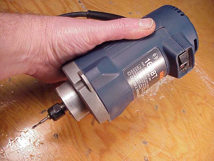
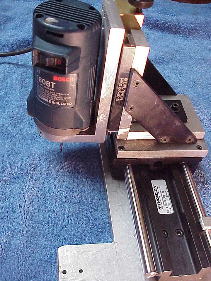
Here's my power unit. It's a regular Bosch laminate trimmer, one I bought when I first decided to retire the old Dremel. I never used it, because it's a bit heavy to use with my old fixture, and the starting torque makes the thing jump almost out of my hand.
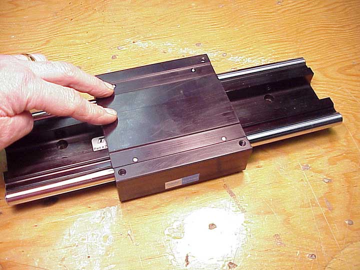
I got out my McMaster-Carr catalog, and ordered up a precision linear slide unit. I figure there's no chance I'd be able to align any kind of bearings this well, so I spent the dough (over $400.00) for the best unit I could find. This baby is rated at 600 lb. working load.
The carriage runs on "recirculating" ball bearing races, with 1/2" hardened steel rails. It's really something. There's absolutely no side play at all, and it glides effortlessly. At that price, it had better!
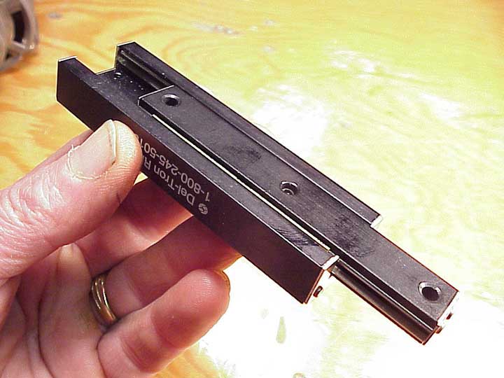
On the next page, I spied this little ball bearing unit. I figured it would be just the ticket for a vertical slide, but being so small, I ordered two, for good lateral stability. Oops! I made a small mistake in my order, so I got two different lengths. Well, I'll just use them anyway, because I really want to get this project done right away. These little slides are each rated at over 200 lb. (And each cost over $200.00, dang it!)
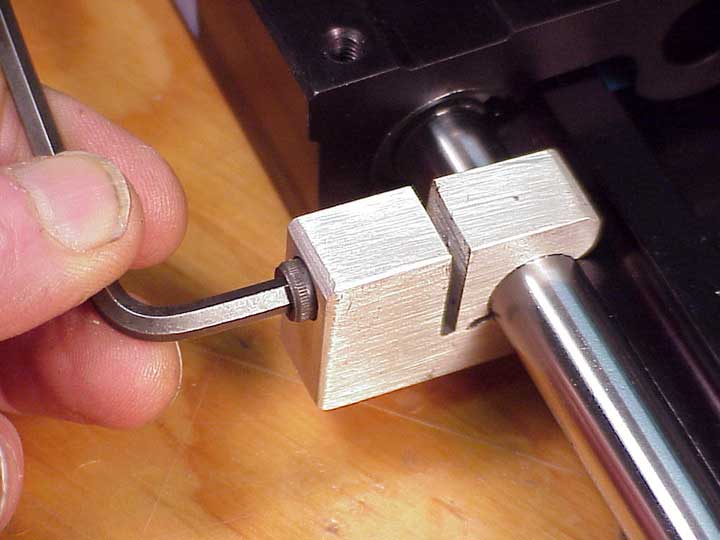
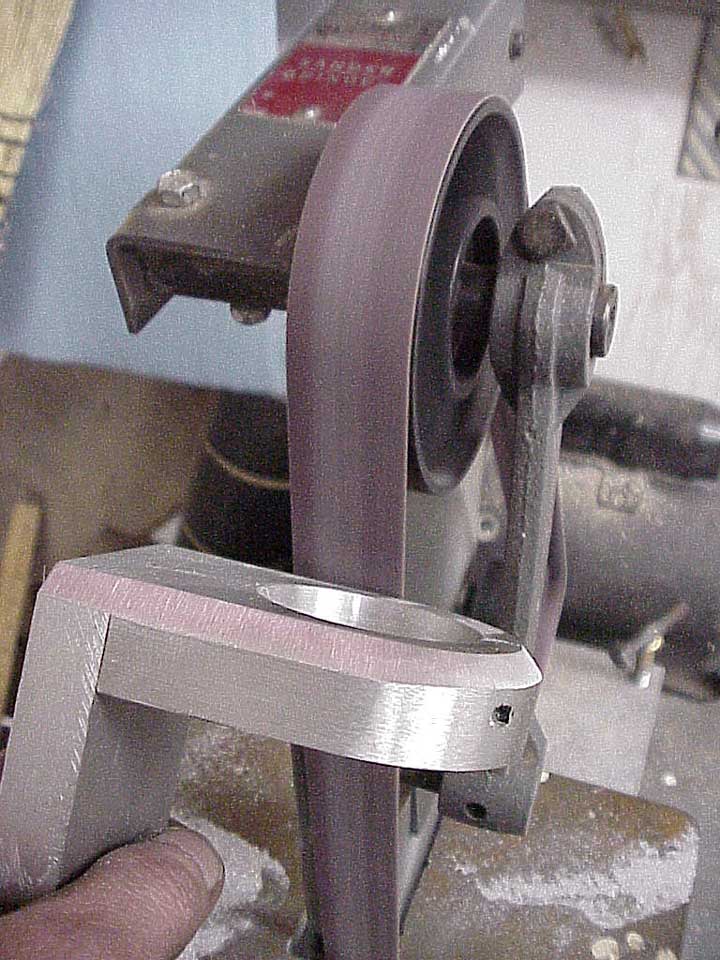
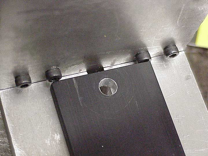
The little slides have built-in end stops, but the big one doesn't. So, to keep the slide from running off the end as I work on this project, I made a couple of aluminum stop clamps. They'll be my stops for the final tool.
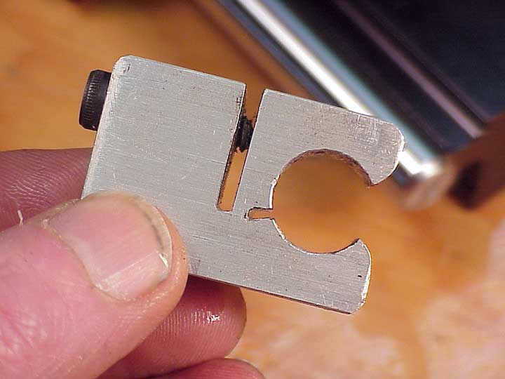
I just cut them out of 1/2" aluminum on my bandsaw after drilling the 1/2" diameter hole. Notice I have it set up as a clamping device, not a setscrew. I don't want to scratch those precious rails.
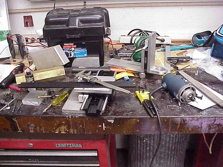
I've been a woodworker all my life, and have done relatively little metal and machine work. One thing I do know is that it's important to keep your bench neat.
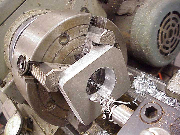
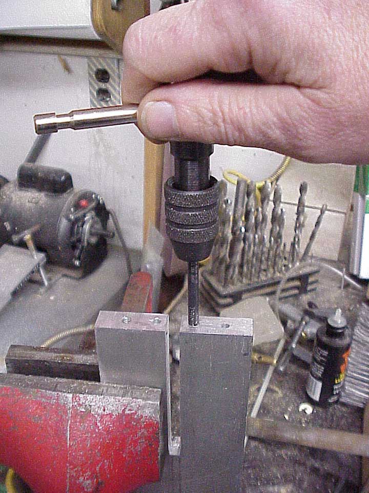
Recently, I bought a used Taiwanese metal lathe, which I've used from time to time on tooling projects. It's my only real metal working machine tool, and I'm still a novice when it comes to working with it. Here, I've chucked a chunk of 1/2" aluminum and I've bored a hole to receive the turned end of the router. This was the only way I could think of to get a round, perpendicular hole. I just counted on the faces of the chuck jaws to be square enough to align the work piece.
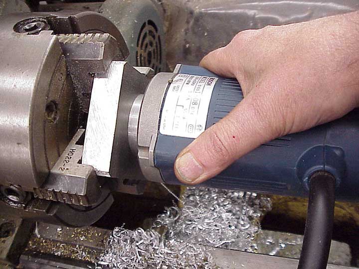
Rather than count on my ability to measure, I just tried the router in the hole until I got a nice fit.
I drilled and counterbored a hole in the piece, before cutting it to shape as a "clamp" to hold the router. Many years ago I learned that I could cut aluminum on my wood cutting bandsaw, because the cutting speed for aluminum is the same as that for wood.
Wow! I don't know why I hadn't thought of it myself, but someone just told me I could also use my table saw for aluminum. Those chips are nasty, but it works reasonably well.
So here's my first bit of joinery. I trued up the butt joint as well as I could, using my little 1"x42" belt sander. Then I drilled and tapped one hole to screw the two parts together. With the parts screwed together, I could drill the other two holes through both parts. That's how I aligned everything on this project. Every time I try to measure and drill, I screw up and parts don't fit.
A little "sculpting" with the sander made my router clamp complete. I tried drawing and planning this tool on paper, but gave up almost immediately. I just can't work that way. Every time I try to visualize how things will fit, I find I'm way off. I seem to get better results by modifying the design to fit how things come out, if that makes any sense.
Because this unit will slide up and down, I was worried that the bit might not be parallel to the sliding action. I chucked in a piece of 1/4" drill rod, rotated it by hand, and measured it height from the cast iron table of my saw.
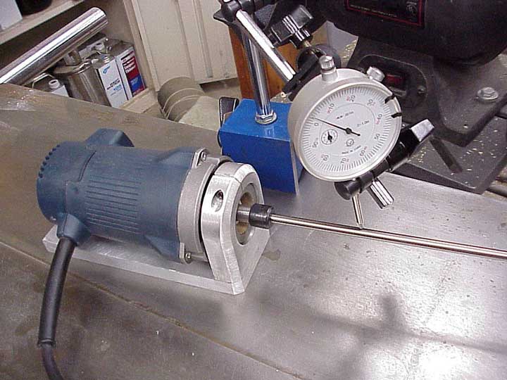
I remembered I'd bought this dial indicator for another project (don't ask!) and found it worked a bit better for measuring. I'm off by about .010" per inch of length. I suspect that'll be close enough for routing bridges, but if it's not, I can later shim the bearings under this slide.
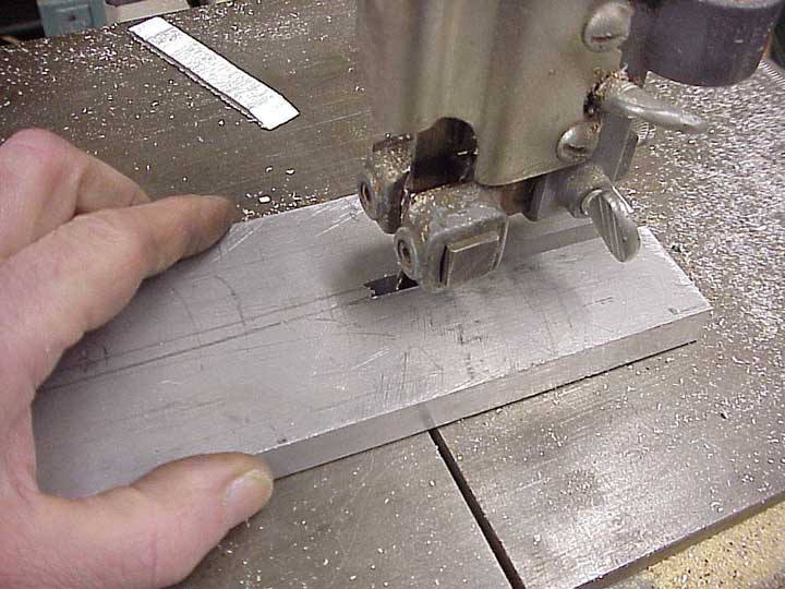
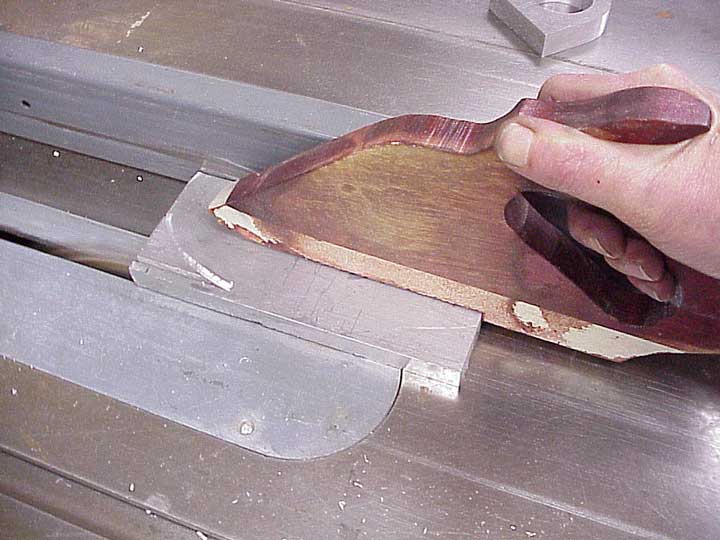
I needed a piece with a slot to make "fore and aft" adjustments once the jig was mounted on a guitar. Not having a better way, I decided to cut the slot on my bandsaw.
Cleaning up the slot with the sander, I got a decent, but not all that straight slot. As with all the parts of this tool, I don't really need precision in my work. I'm counting on the ball bearing slides
OK, a 1/4-20 bolt slides up and down in the slot.
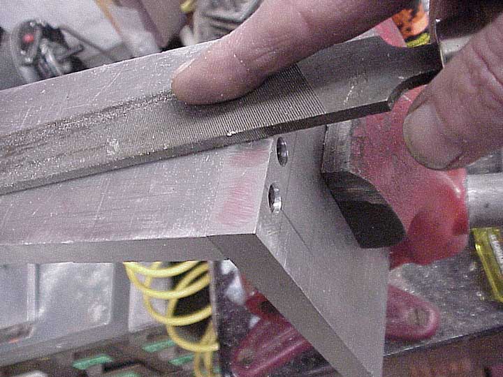
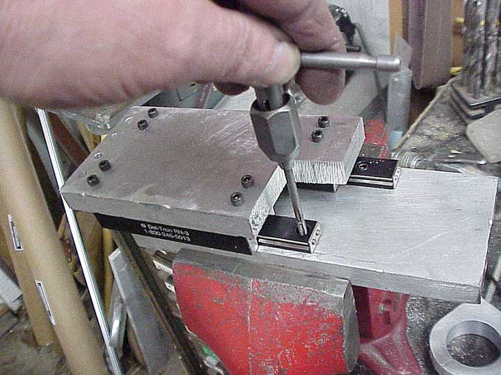
The next few photos illustrate how I join parts. I'm not going to show each and every part or operation on this project, because I'd have hundreds more photographs to process. Also, I'm not suggesting that you make this tool. I hope you might grab an idea or two about the process, though. Here, I'm just checking the end for "squareness."
I really like those hex socket cap screws. Some years ago, I bought an assortment of 1/4-20 and 10-24 screws, along with their associated taps and counterbores. Great to have 'em around. I've drilled four holes, and counterbored them to receive the screw heads. Next, I drilled through the holes to spot the centers of the piece to which this will be bolted.
I then drilled the proper hole in the mating piece, and tapped the holes by hand. If the tap isn't dead on straight, things still fit together OK, and the bolts will flex a bit as the two parts draw together.
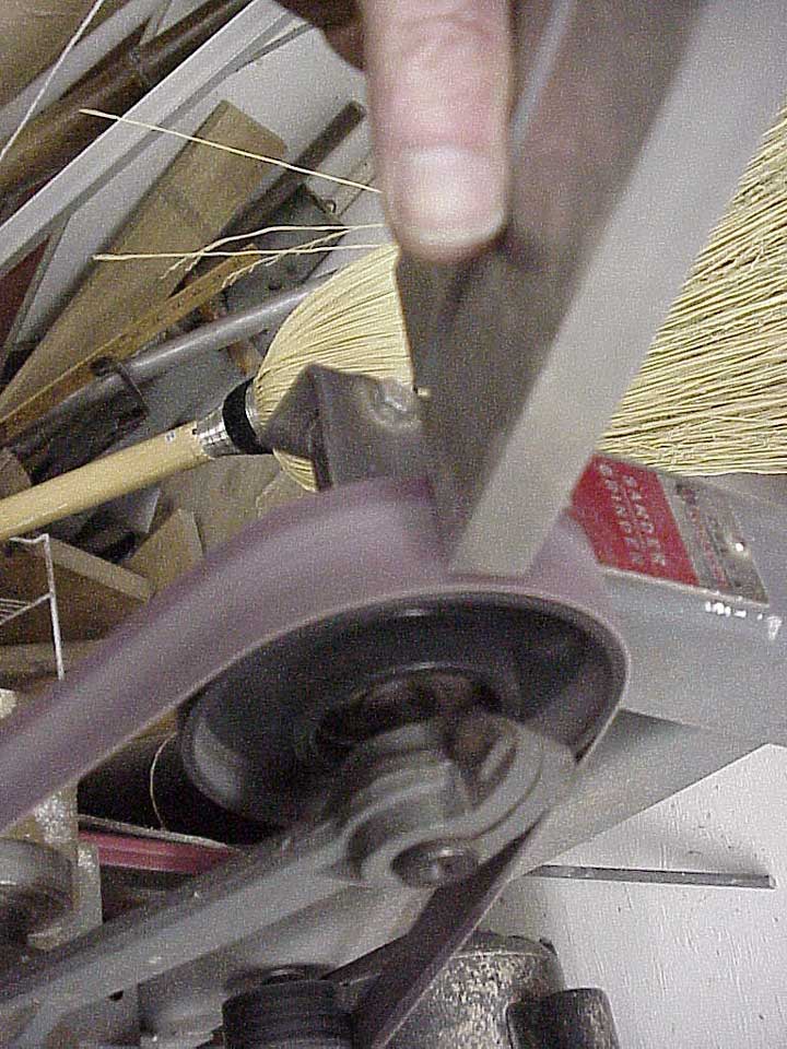
Not being able to make a truly flat surface on the end, I simply hollowed it a bit on my sander, just the way I would if it were a piece of maple. I don't know if machinists ever do this kind of thing, but it works for me. . .
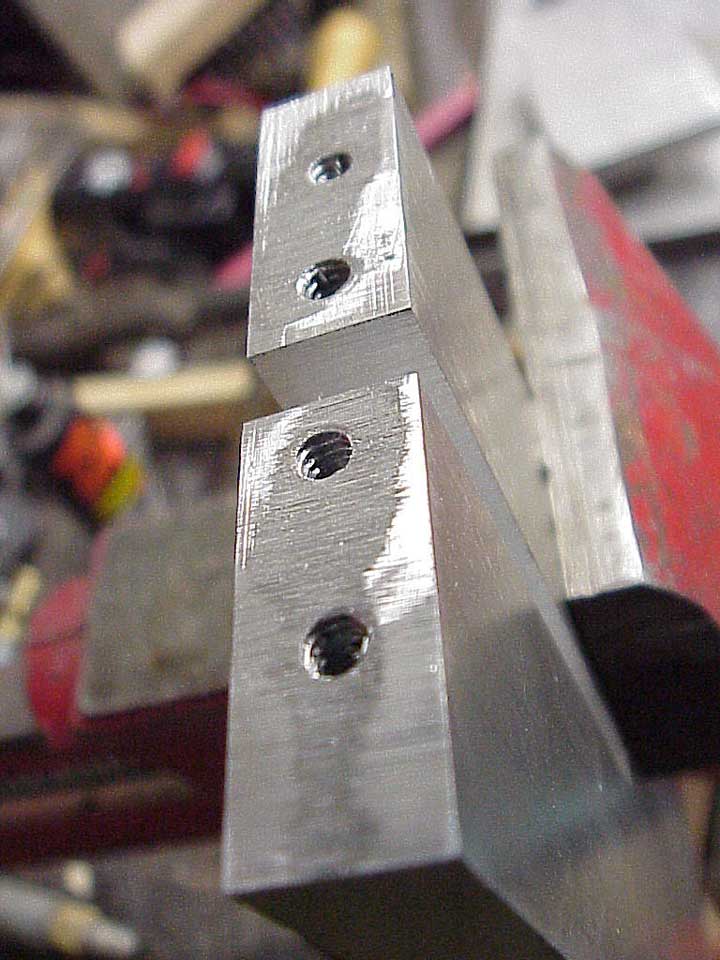
So, as the two pieces are bolted up, this one will bear more or less on the outside edges, and I'll get reasonable support, without "rocking."
Naturally, the end didn't line up well, but I fixed that!
So, that's pretty much how I did the joinery.
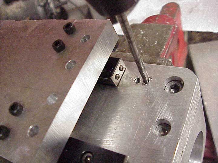
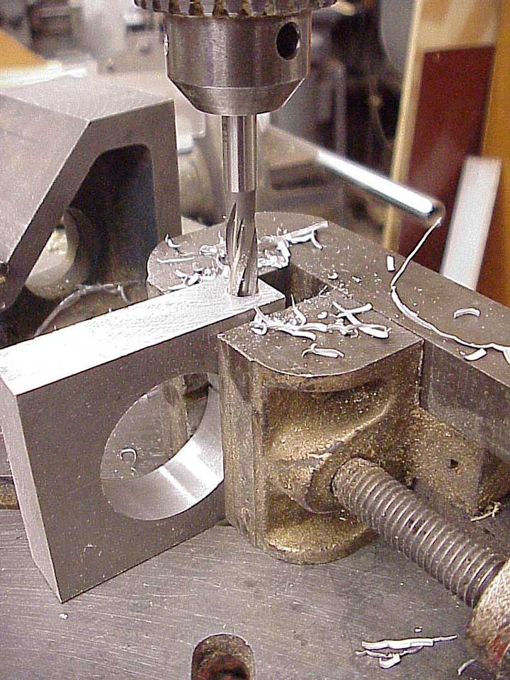
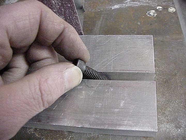
I needed to tap some little 6-32 holes to mount the small slides, so I went at it fearlessly. Oops, got one in the wrong place, a little too much toward the outside. Well, I can always move down a bit, and start again.
Ouch!
Now, I broke the tap off in my new hole. Well, there's still a bit more room. I'll just move down a bit more. . .
Most of the time, though, I was able to hold the part in place to make sure things lined right up as I drilled and tapped mounting holes.
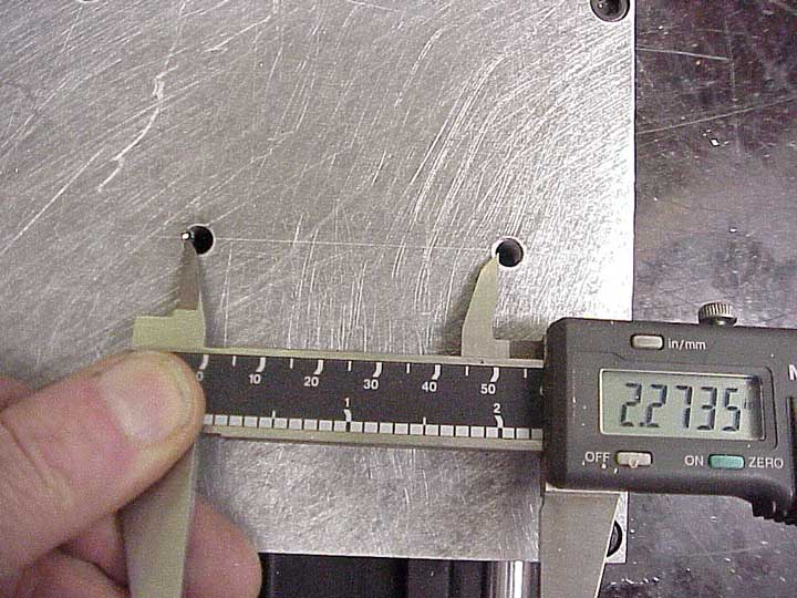
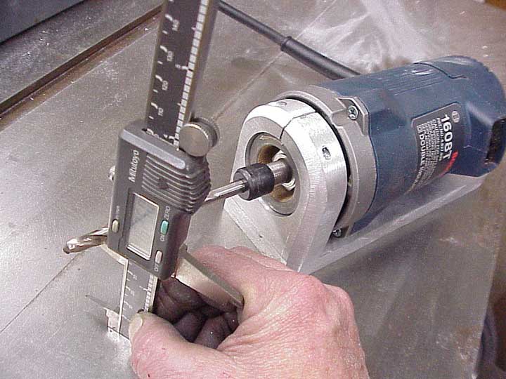
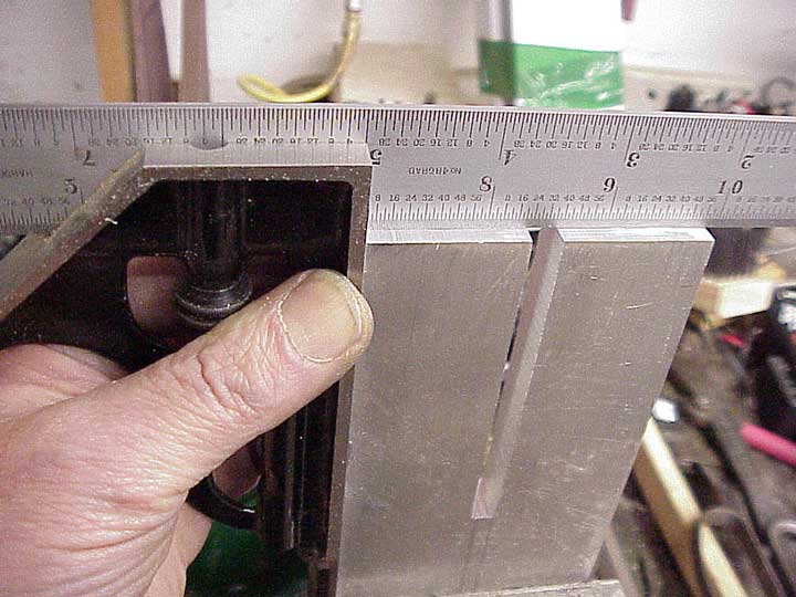
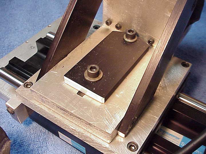
For my base slide adjustment, I needed to transfer a measurement from the base to a clamping plate. I did it the same way I measure for guitar tuner hole spacing. I set my calipers to measure from left edge to left edge. I don't trust myself to try to measure the center of the hole.
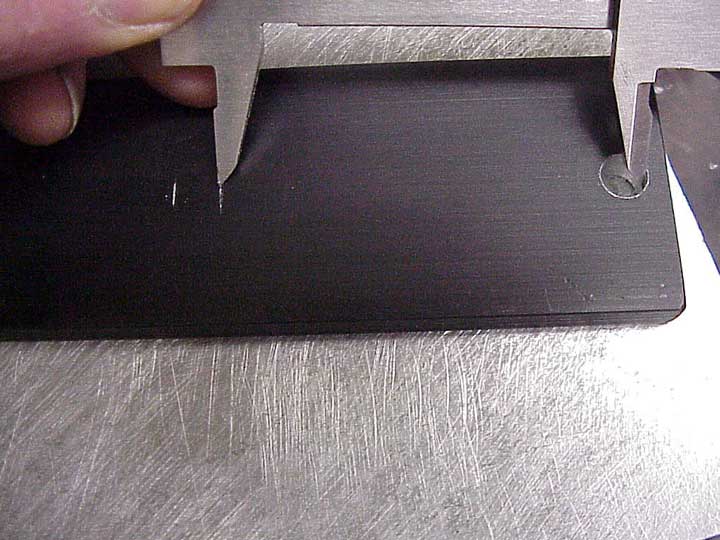
Without actually reading the caliper, I transferred the measurement. I'd already drilled one hole in the plate, so I measured from each edge of the hole, and swung the caliper like a trammel, scribing a little line.
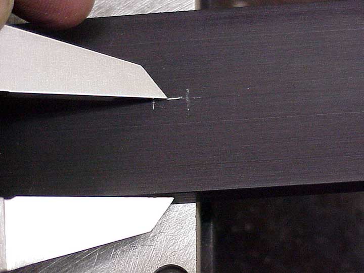
Then I set my caliper to half the width of my little plate, and scribed again.
From here, I just eyeballed it. I figure I can guess the center of this little space within the tolerance of my wandering drill bit when I'm working on the drill press.
Then, drilling the second hole, my clamping plate is complete.
Well, almost. I forgot those little slide mounting screws, which are neatly in the way.
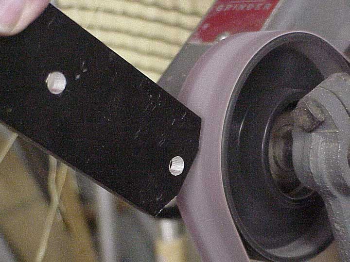
Time for another design change. A quick bit of grinding will take care of that problem
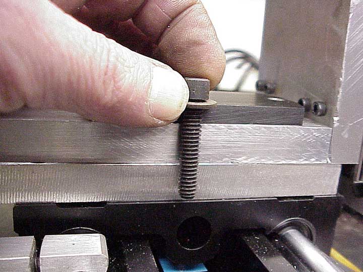
Now I see why they make washers. They're useful to keep screws from bottoming out.
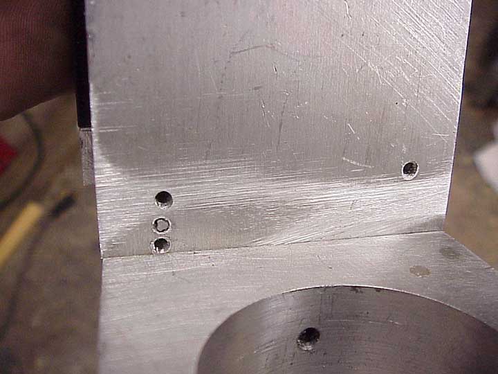
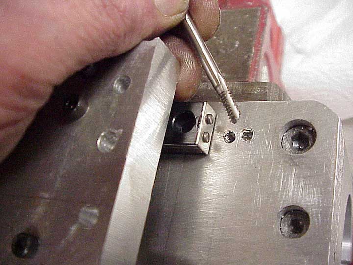
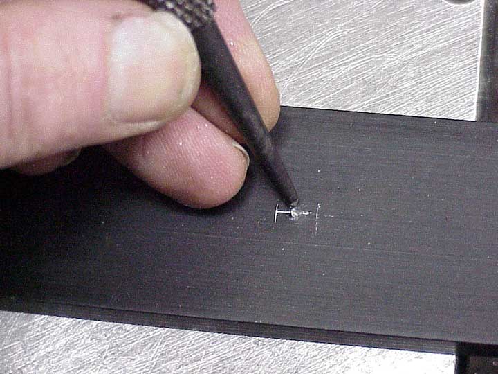
Oh, yes, take a look at this neat piece of work. Here's my little trio screw holes, with the broken tap in the center.
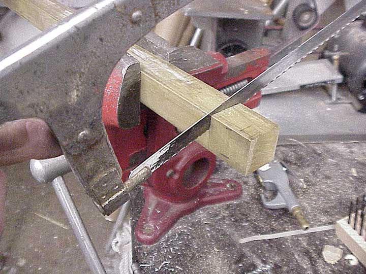
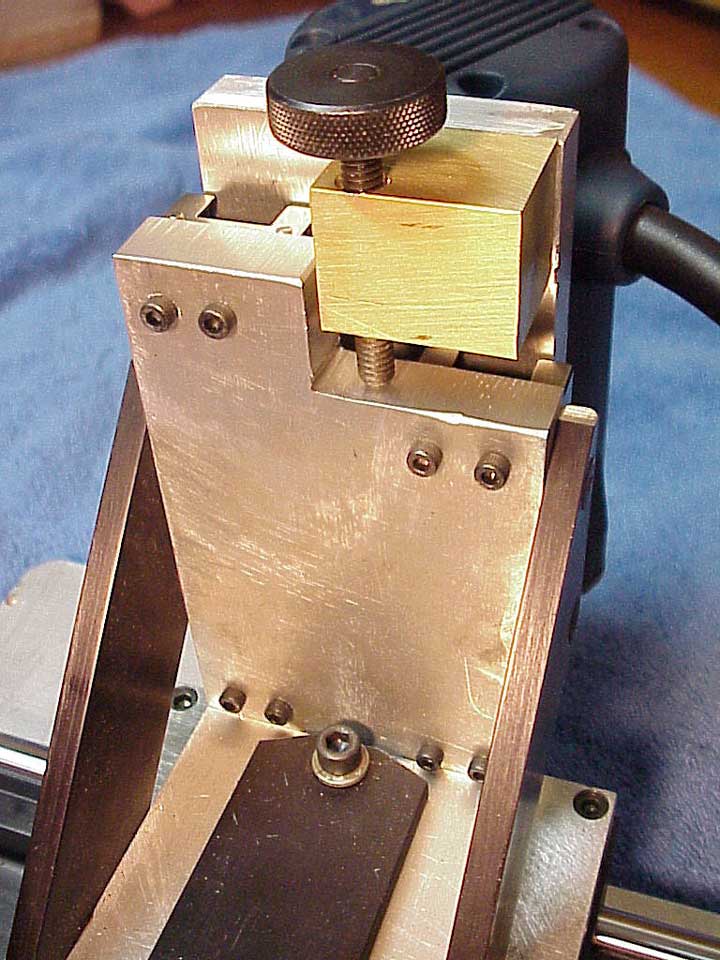
I found a big hunk of one-inch square brass that should work for my vertical adjustment.
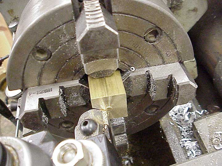
Couldn't cut it straight by hand, and can't use the woodworking power tools on brass, so I squared it up on the lathe, which still had the four jaw chuck in place. I didn't bother to center it, because I was only squaring off the end.
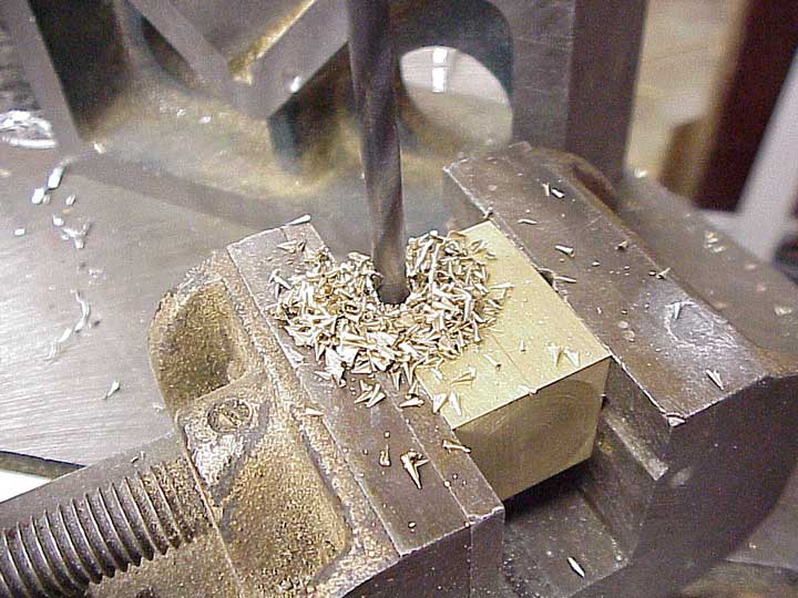
Drilling and tapping brass is fun. Look at those chips. It's almost like working with mahogany. Everything seems to work so much easier and cleaner.
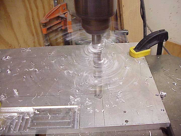
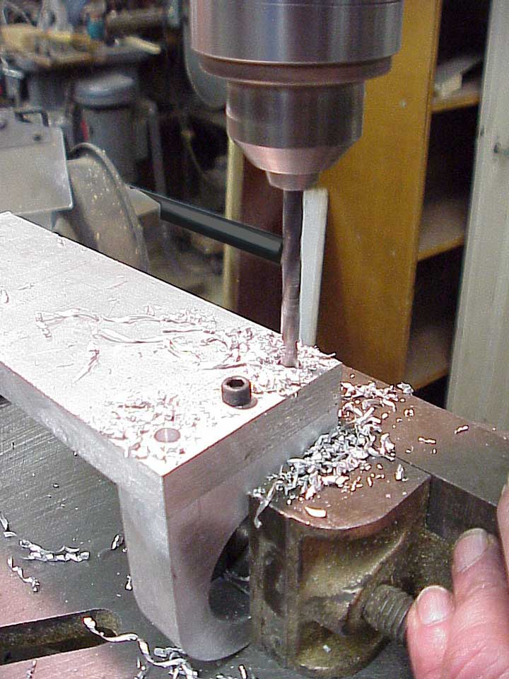
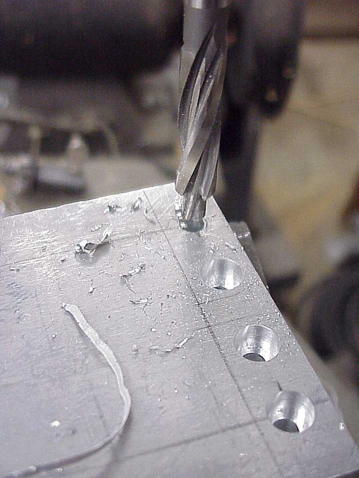
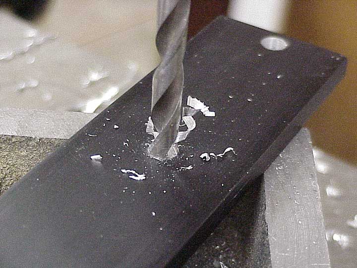
Working aluminum is more like machining Brazilian rosewood. It's gummy, and nasty. Just look at that big sharp stringy mass spinning around! Here, I'm drilling the aluminum base plate. It's just another piece of aluminum salvage, as is most of the rest of this tool.
Well, it only took the better part of a couple of days to put this together, but my first impression is that I waited about ten years too long to get this project done!
It's really simple - just a carriage that slides sideways, and a holder that slides up and down. Because of its mass, and the smooth, tight bearings, it runs with virtually no vibration, and cuts a really straight, smooth, true slot.
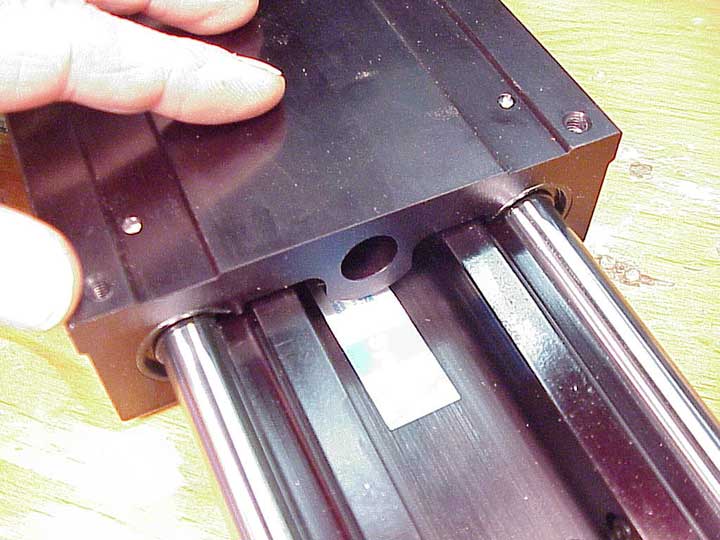
In case you're wondering, here's the label on the small bearings, McMaster-Carr part numbers 6257K18, and 6257K19. I had originally assumed I'd use a second big Thomson slide for the vertical adjustment, but when I saw these in the catalog, it was clear I could save a lot of space and weight.
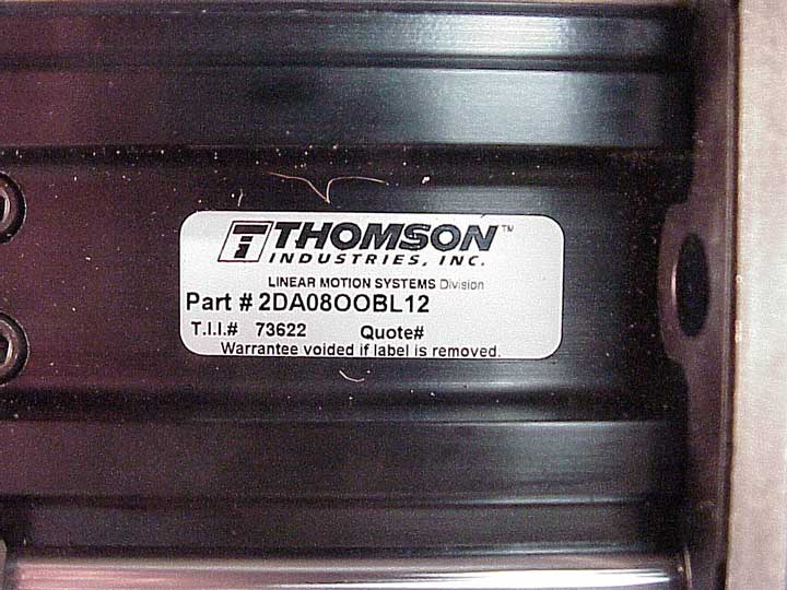
This big slide is McMaster-Carr number 6109K1
So, as you can see, the big bottom slide is mounted on a 1/2" aluminum plate. It measures 15-1/4" x 7", because that's the size it was when I found it. I made an arbitrary 2-1/2" x 8" cutout under the router, which should clear most any guitar bridge.
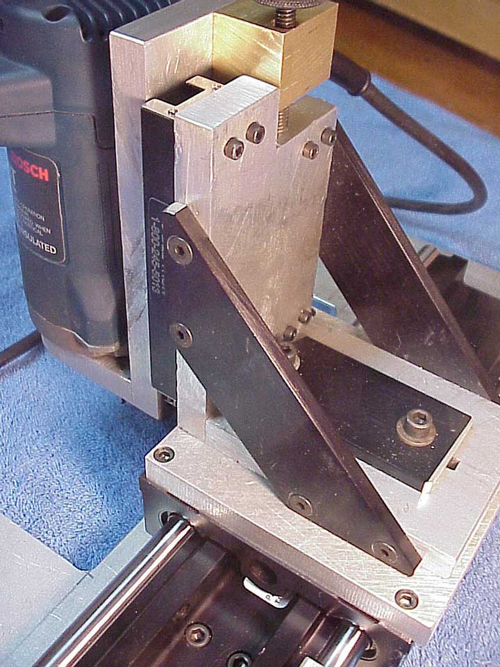
Here's the carriage from the back side. The diagonal plates and the slide clamping plate are 1/4" thick anodized black aluminum scrap. Most all the rest was made from 1/2" thick aluminum salvage. I buy most of my aluminum from a local metal salvage yard, so I don't know (or much care) about alloy, or precise dimension.
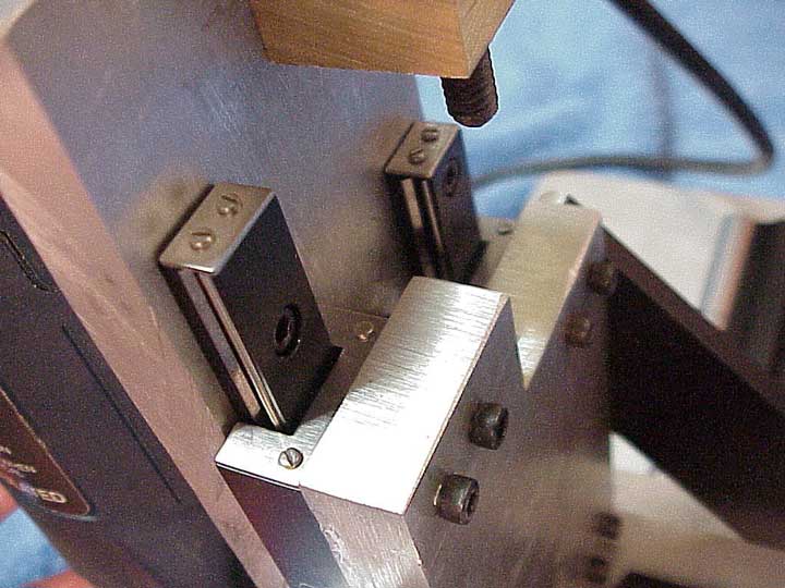
If I hold up the vertical slide, you can see the two different length linear bearings. I tried to turn the accident of a mistaken order into lemonade by working the vertical stop screw adjustment in an asymmetrical orientation.
I'll be able to insert measured spacers under the stop screw so I can plunge to precise depths. After a few trial cuts, I'm ready to give this tool a real test in the shop.

Oh, yes, on the bottom, I've stuck a layer of 1/8" leather for to keep the tool from skating around and to protect the guitar's finish. As usual, I thought of a few more holes to drill after I already had the leather stuck there with contact cement.
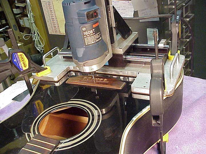
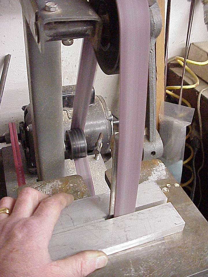
Here's the tool in place, doing its job. I simply clamp it there with four mini Quick Grip clamps. As you can see, there's lots of clearance around the cutter for great visibility.
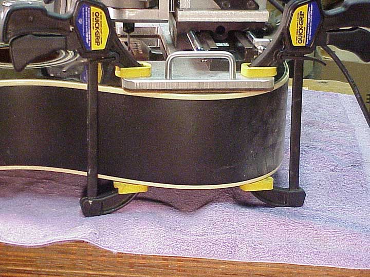
The four clamps act as support feet, holding the guitar firmly in place on my bench.
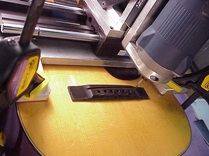
This is a tiny 3/4 size Martin 5-18. The guitar is so small that the tool doesn't fit below the bridge, but it's no problem to use it the other way around. Sure enough, the sheer mass of the tool makes it a snap to rout a clean, full depth slot with no vibration or wandering even with a 1/8" shank bit. I'll be using 3/16" shank end mills most of the time, though, for extra rigidity.
Let me reiterate once again. I'm no expert on tooling, and only I wanted to present this little piece just to give an idea of how I "get by" in metal working. If I had the skill and the mill, I'm sure I could make adequate slides and other devices which would bring the cost of this kind of tool into a reasonable range. Fact is, though, it fit me the way it is. In another year (or perhaps in another life) maybe I'll get into more serious machining, because it's a great thrill to put together a really good tool I've wanted for a special job!